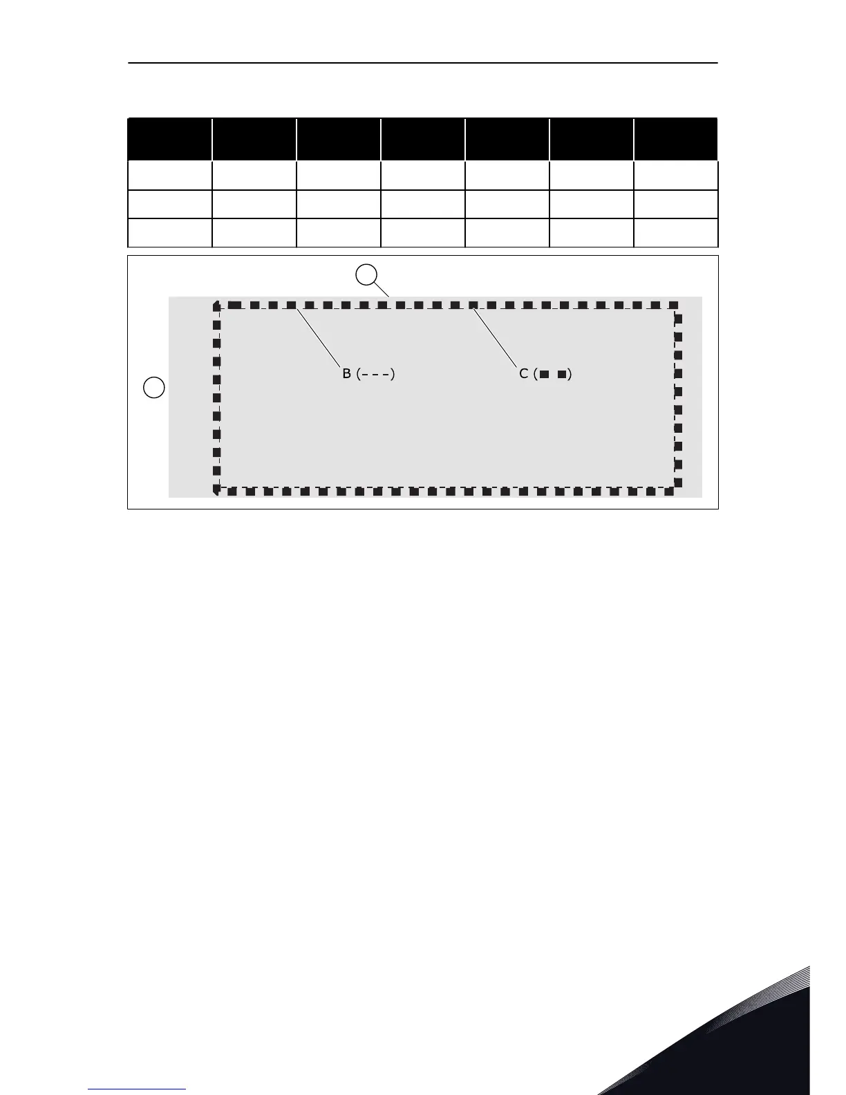
Table 9: The dimensions of the opening for the flange mounting
Enclosure
size
A [mm] B [mm] E [mm] A [in] B [in] E [in]
MR8 859 298 18 33.8 11.7 0.7
MR9 975 485 54 38.4 19.1 2.1
MR10 960 510 122 37.8 20.1 4.8
Fig. 20: Sealing of the opening for MR8, MR9, and MR10
A. The AC drive
B. The outline of the opening
C. Gasket tape
D. The top of the drive
5.2.3 INSTALLING A DETACHED CONTROL UNIT
Use the installation kit for a detached control unit (ENC-QCDU) with MR10 and MR12 to
install the control unit separate from the power unit. The control unit must be installed in an
enclosure that is similar to the one where the power unit is installed.
The installation kit includes these components:
•
assembly plate
•
side plate
•
2-meter cable
•
screws
See dimensions in Fig. 11.
THE INSTALLATION PROCEDURE
1 Attach the cable to the assembly plate. Make sure
that you connect the cable so that the cable points
to the edge.
INSTALLATION INTO CABINET VACON · 41
LOCAL CONTACTS: HTTP://DRIVES.DANFOSS.COM/DANFOSS-DRIVES/LOCAL-CONTACTS/
5
 Loading...


