EasyManuals Logo

Vacon 100 flow Installation Manual

Vacon 100 flow
128 pages
To Next Page IconTo Next Page
To Previous Page IconTo Previous Page
Page #106 background imageLoading...
Page #106 background image
I
L
I
L*110%
1 min 9 min
I
t
I
L*110%
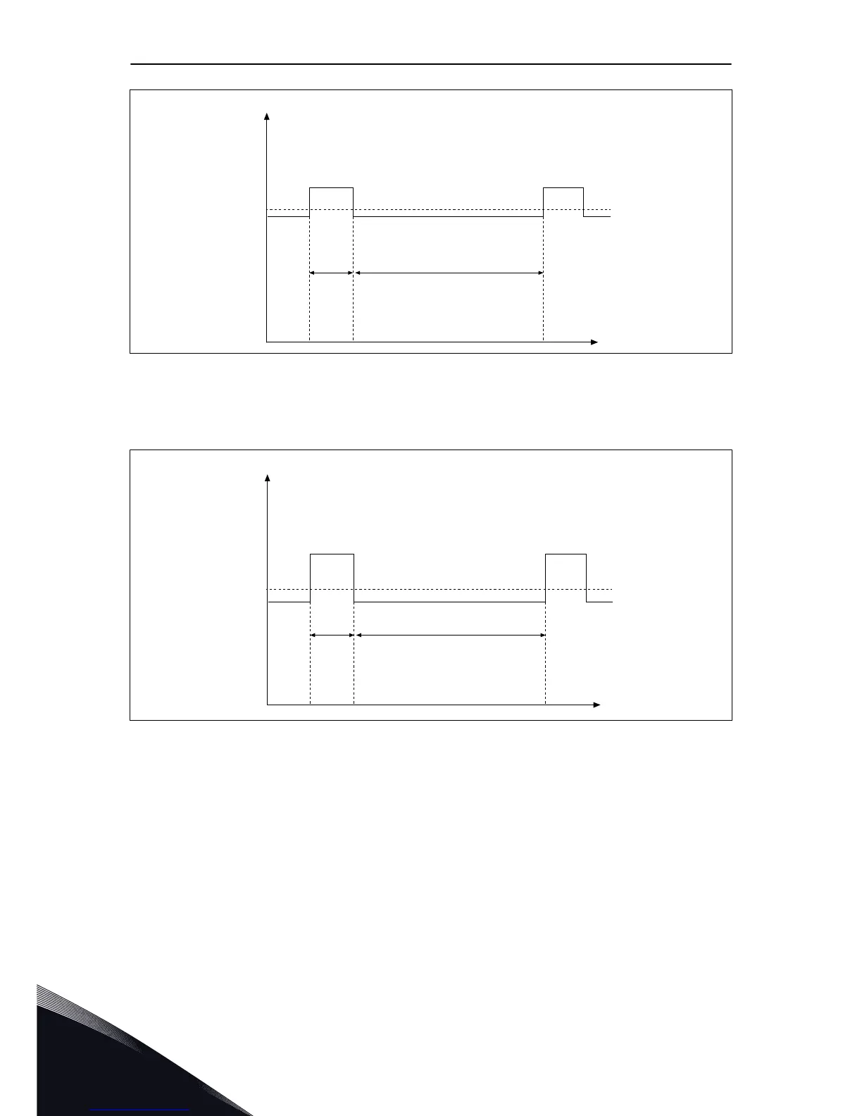
Fig. 33: Low overload
The high overload means that if 150% of the continuous current (I
H
) is required for 1 minute
every 10 minutes, the remaining 9 minutes must be approximately 92% of I
H
or less. This is to
make sure that the output current is not more than I
H
during the duty cycle.
I
H
I
H*150%
1 min 9 min
I
H*150%
I
t
Fig. 34: High overload
For more information, refer to the standard IEC61800-2 (IEC:1998).
9.1.5 BRAKE RESISTOR RATINGS
Make sure that the resistance is higher than the set minimum resistance. The power
handling capacity must be sufficient for the application.
VACON · 106 TECHNICAL DATA, VACON® 100 INDUSTRIAL
9
LOCAL CONTACTS: HTTP://DRIVES.DANFOSS.COM/DANFOSS-DRIVES/LOCAL-CONTACTS/

Table of Contents

Other manuals for Vacon 100 flow

Questions and Answers:

Question and Answer IconNeed help?

Do you have a question about the Vacon 100 flow and is the answer not in the manual?

Vacon 100 flow Specifications

General IconGeneral
Protection classIP20
Communication interfaceRS-485
Operating temperature-10°C to +50°C
Storage temperature-40°C to +70°C
Ambient temperature-10°C to +40°C
Control methodSensorless vector control
Communication protocolsCANopen
ApprovalsCE, UL
I/O2 analog inputs
Protection featuresOvercurrent, overvoltage, undervoltage, overtemperature
Frequency range0 Hz to 400 Hz
Humidity5% to 95%, non-condensing
Voltage range208-240 V

Related product manuals