It is possible to use the drive with an external power source with these properties: +24 VDC
±10%, minimum 1000 mA. Connect the external power source to terminal 30. This voltage is
sufficient to keep the control unit on and for you to set the parameters. The measurements
of the main circuit (for example, the DC link voltage, and the unit temperature) are not
available when the drive is not connected to mains.
The status LED of the drive shows the status of the drive. The status LED is located in the
control panel, below the keypad, and it can show 5 different statuses.
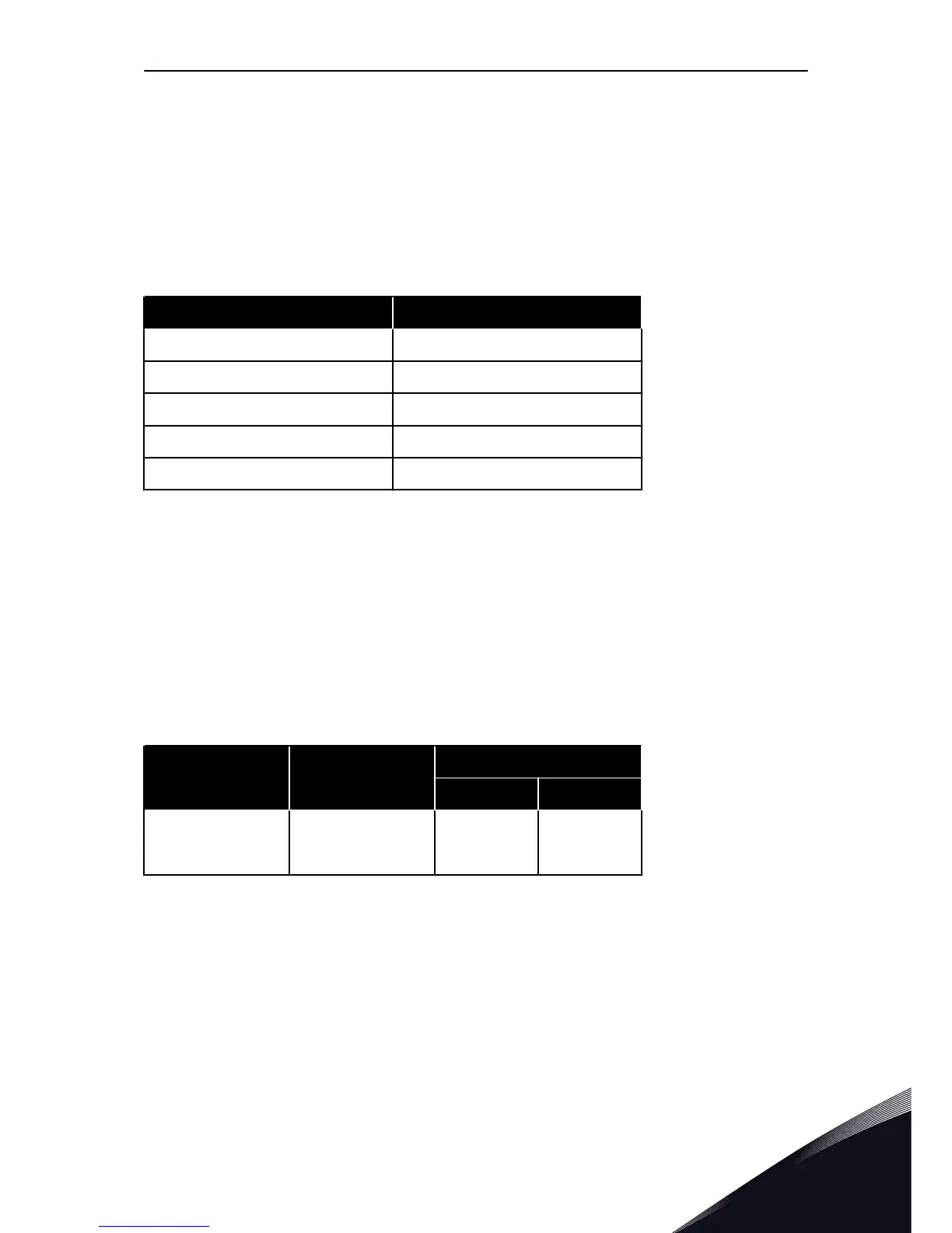
Table 27: The statuses of the status LED of the drive
Colour of the LED light Status of the drive
Blinking slowly Ready
Green Run
Red Fault
Orange Alarm
Blinking fast Downloading software
7.2 CONTROL UNIT CABLING
The standard I/O board has 22 fixed control terminals and 8 relay board terminals. You can
see the standard connections of the control unit and the descriptions of signals in Fig. 26.
7.2.1 SELECTION OF THE CONTROL CABLES
The control cables must be a minimum of 0.5 mm
2
screened multicore cables. See more on
the cable types in 6.1.1 Cable and fuse sizes. The terminal wires must be a maximum of 2.5
mm
2
for the relay board terminals and other terminals.
Table 28: The tightening torques of the control cables
The terminal The terminal screw The tightening torque
Nm lb-in.
All the terminals of
the I/O board and the
relay board
M3 0.5 4.5
7.2.2 CONTROL TERMINALS AND DIP SWITCHES
Here you see the basic description of the terminals of the standard I/O board and the relay
board. For more information, see 11.1 Technical data on control connections.
Some terminals are assigned for signals that have optional functions that you can use with
the DIP switches. See more in 7.2.2.1 Selection of terminal functions with DIP switches.
CONTROL UNIT VACON · 75
LOCAL CONTACTS: HTTP://DRIVES.DANFOSS.COM/DANFOSS-DRIVES/LOCAL-CONTACTS/
7

 Loading...


