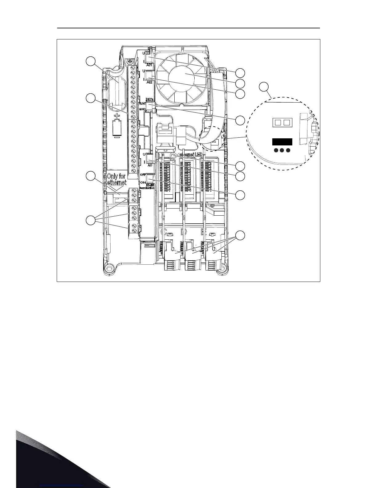
Fig. 25: The components of the control unit
A. The control terminals for the standard
I/O connections
B. The Ethernet connection
C. The relay board terminals for 3 relay
outputs or 2 relay outputs and a
thermistor
D. The option boards
E. A DIP switch for the RS485 bus
termination
F. A DIP switch for the signal selection of
Analogue Output
G. A DIP switch for the isolation of the
digital inputs from ground
H. A DIP switch for the signal selection of
Analogue Input 2
I. A DIP switch for the signal selection of
Analogue Input 1
J. The status indicator of the Ethernet
connection
K. A fan (only in IP54 of MR4 and of MR5)
L. The battery for the RTC
M. The location and the default position of
the Safe Torque Off (STO) jumper
When you receive the AC drive, the control unit contains the standard control interface. If you
included special options in your order, the AC drive will be as in your order. On the next
pages, you will find information on the terminals and general wiring examples.
VACON · 74 CONTROL UNIT
7
LOCAL CONTACTS: HTTP://DRIVES.DANFOSS.COM/DANFOSS-DRIVES/LOCAL-CONTACTS/
 Loading...


