EasyManuals Logo

Vacon 100 flow Installation Manual

Vacon 100 flow
128 pages
To Next Page IconTo Next Page
To Previous Page IconTo Previous Page
Page #40 background imageLoading...
Page #40 background image
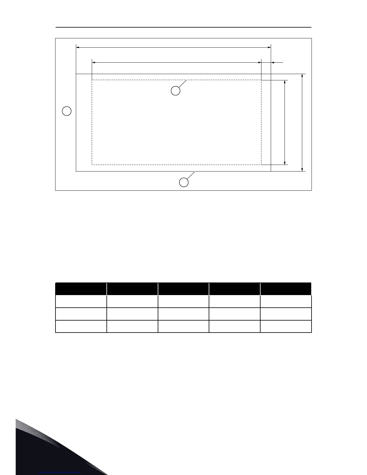
Fig. 19: The dimensions of the opening and drive module outline with flange
A. The height of the opening for the flange
mounting
B. The width of the opening
C. The height of the drive module
D. The width of the drive module
E. The distance between the bottom of the
drive module and the bottom of the
opening
F. The outline of the opening
G. The outline of the drive module
H. The top of the drive module
Table 8: The dimensions of the drive module
Enclosure size C [mm] D [mm] C [in] D [in]
MR8 898 359 35.4 14.1
MR9 1060 550 41.7 21.7
MR10 1110 576 43.7 22.7
VACON · 40 INSTALLATION INTO CABINET
5
LOCAL CONTACTS: HTTP://DRIVES.DANFOSS.COM/DANFOSS-DRIVES/LOCAL-CONTACTS/

Table of Contents

Other manuals for Vacon 100 flow

Questions and Answers:

Question and Answer IconNeed help?

Do you have a question about the Vacon 100 flow and is the answer not in the manual?

Vacon 100 flow Specifications

General IconGeneral
Protection classIP20
Communication interfaceRS-485
Operating temperature-10°C to +50°C
Storage temperature-40°C to +70°C
Ambient temperature-10°C to +40°C
Control methodSensorless vector control
Communication protocolsCANopen
ApprovalsCE, UL
I/O2 analog inputs
Protection featuresOvercurrent, overvoltage, undervoltage, overtemperature
Frequency range0 Hz to 400 Hz
Humidity5% to 95%, non-condensing
Voltage range208-240 V

Related product manuals