EasyManuals Logo

Vacon 100 flow Installation Manual

Vacon 100 flow
128 pages
To Next Page IconTo Next Page
To Previous Page IconTo Previous Page
Page #35 background imageLoading...
Page #35 background image
NOTE!
The optional external power connection block is not necessary if you have an
options module.
B
C D
E
C
D
E
G
A
F
2L1 2L22L3
PE W/T3V/T2U/T1
PE
L1 L2 L3PE
1L11L2 1L3PE
L1 L2 L3PE
DC-DC+
COM
STO
COM
STO
OK
3
M
DC-
DC+
R-
DC-
DC+
R-
PE W/T3V/T2U/T1DC-DC+
PE W/
T3
V/
T2
U/
T1
DC-DC+/R-
R+
PE W/
T3
V/
T2
U/
T1
DC-DC+/R-
R+
W1V1U1PE
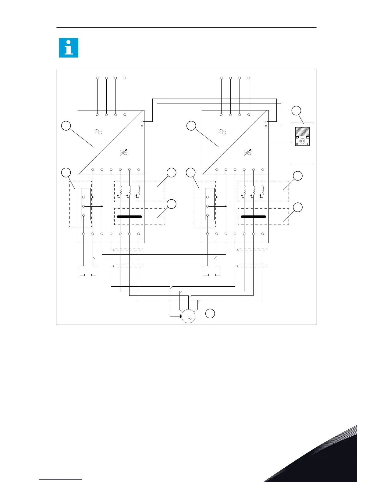
Fig. 16: The main circuit diagram, MR12 with the options module and options
A. The power unit 1
B. The power unit 2
C. The optional brake choppers
D. The optional du/dt filter
E. The optional common mode filter
F. The control unit
G. Symmetrical motor cabling. The cables
must have the same length from the
power unit to a common point of
coupling.
INSTALLATION INTO CABINET VACON · 35
LOCAL CONTACTS: HTTP://DRIVES.DANFOSS.COM/DANFOSS-DRIVES/LOCAL-CONTACTS/
5

Table of Contents

Other manuals for Vacon 100 flow

Questions and Answers:

Question and Answer IconNeed help?

Do you have a question about the Vacon 100 flow and is the answer not in the manual?

Vacon 100 flow Specifications

General IconGeneral
Protection classIP20
Communication interfaceRS-485
Operating temperature-10°C to +50°C
Storage temperature-40°C to +70°C
Ambient temperature-10°C to +40°C
Control methodSensorless vector control
Communication protocolsCANopen
ApprovalsCE, UL
I/O2 analog inputs
Protection featuresOvercurrent, overvoltage, undervoltage, overtemperature
Frequency range0 Hz to 400 Hz
Humidity5% to 95%, non-condensing
Voltage range208-240 V

Related product manuals