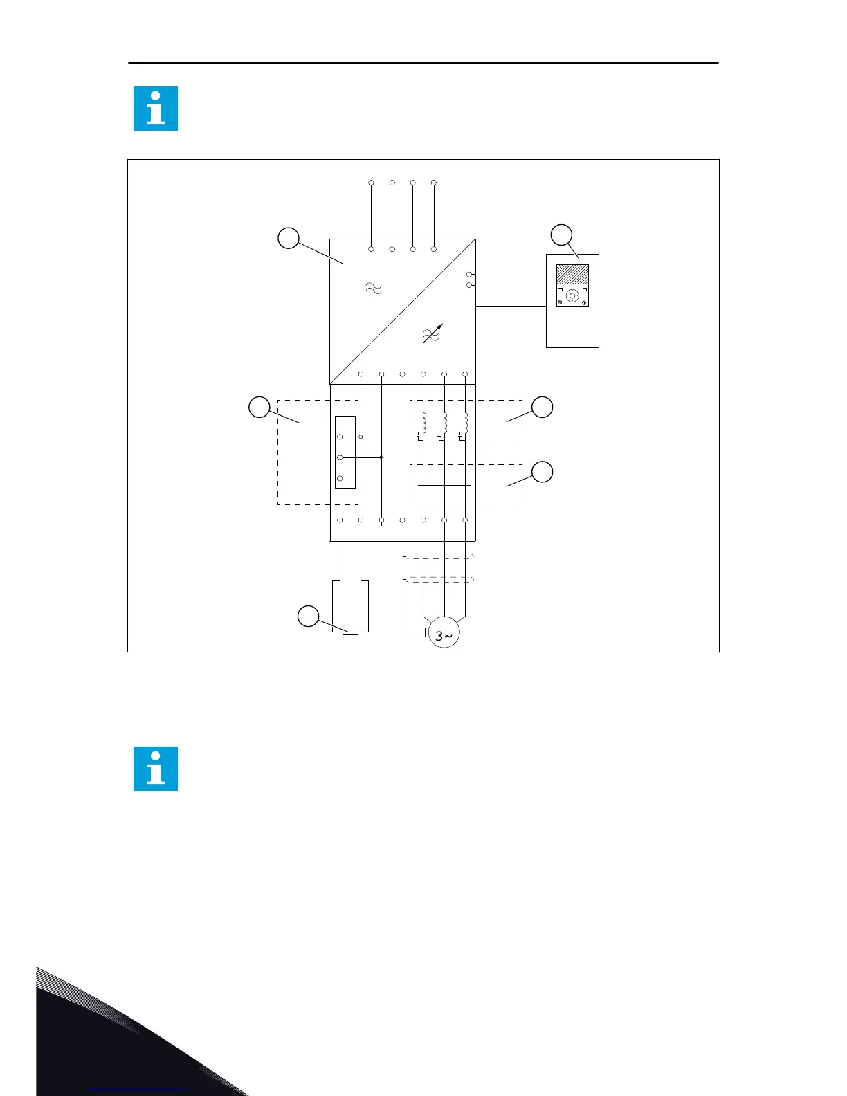
Fig. 14: The main circuit diagram, MR10 with the options module and options
A. The power unit
B. The control unit
C. The optional du/dt filter
D. The optional common mode filter
E. The optional brake chopper
F. The brake resistor
NOTE!
The common mode filter is only used as an additional protection. The basic
protection against motor bearing currents is an insulated bearing.
VACON · 32 INSTALLATION INTO CABINET
5
LOCAL CONTACTS: HTTP://DRIVES.DANFOSS.COM/DANFOSS-DRIVES/LOCAL-CONTACTS/
 Loading...


