ROBOT HP7E / HP10E / HP12E / HP15E / HP20E 2. Description
2-3© VEMAG 2010
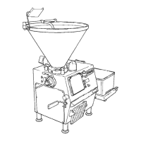
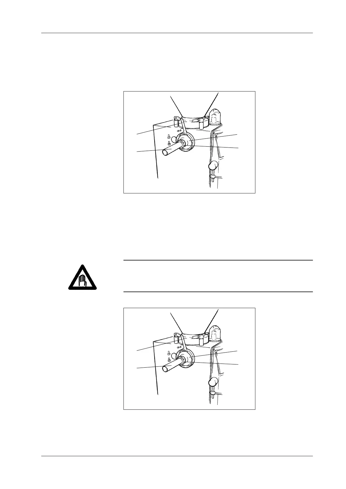
2.2.4 Filling horn holder
The machine is tted with a lling horn holder (1) at the outlet as standard
and this is locked at the outlet by the locking nut (2). The lling horn (3)
is attached to the lling horn holder with the aid of the lling horn nut (4).
The product is ejected through the lling horn by the double screws.
1 Filling horn holder
2 Locking nut
3 Filling horn
4 Filling horn nut
Fig. 2-4
Machine with lling horn
holder
1
2
3
4
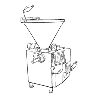
2.2.5 Linking gear (optional)
The linking gear (1) is attached to the housing of the machine with the aid
of two bearing journals (2) and swivelled in front of the outlet. It is locked
in position at the outlet with the locking nut (3) like the lling horn holder.
The linking horn (4) is attached to the linking gear with the aid of linking
nut (5).
Danger!
To prevent injury, do not use linking horns with sprung heads. Use only
completely straight, undamaged linking horns and use the appropriate
test program to check the linking horn selected before starting production.
1 Linking gear
2 Bearing journals
3 Locking nut
4 Linking horn
5 Linking nut
Fig. 2-5
Machine with linking gear
(optional)
1
2
3
4
 Loading...