ROBOT HP7E / HP10E / HP12E / HP15E / HP20E 3. Installation and commissioning
3-7© VEMAG 2010
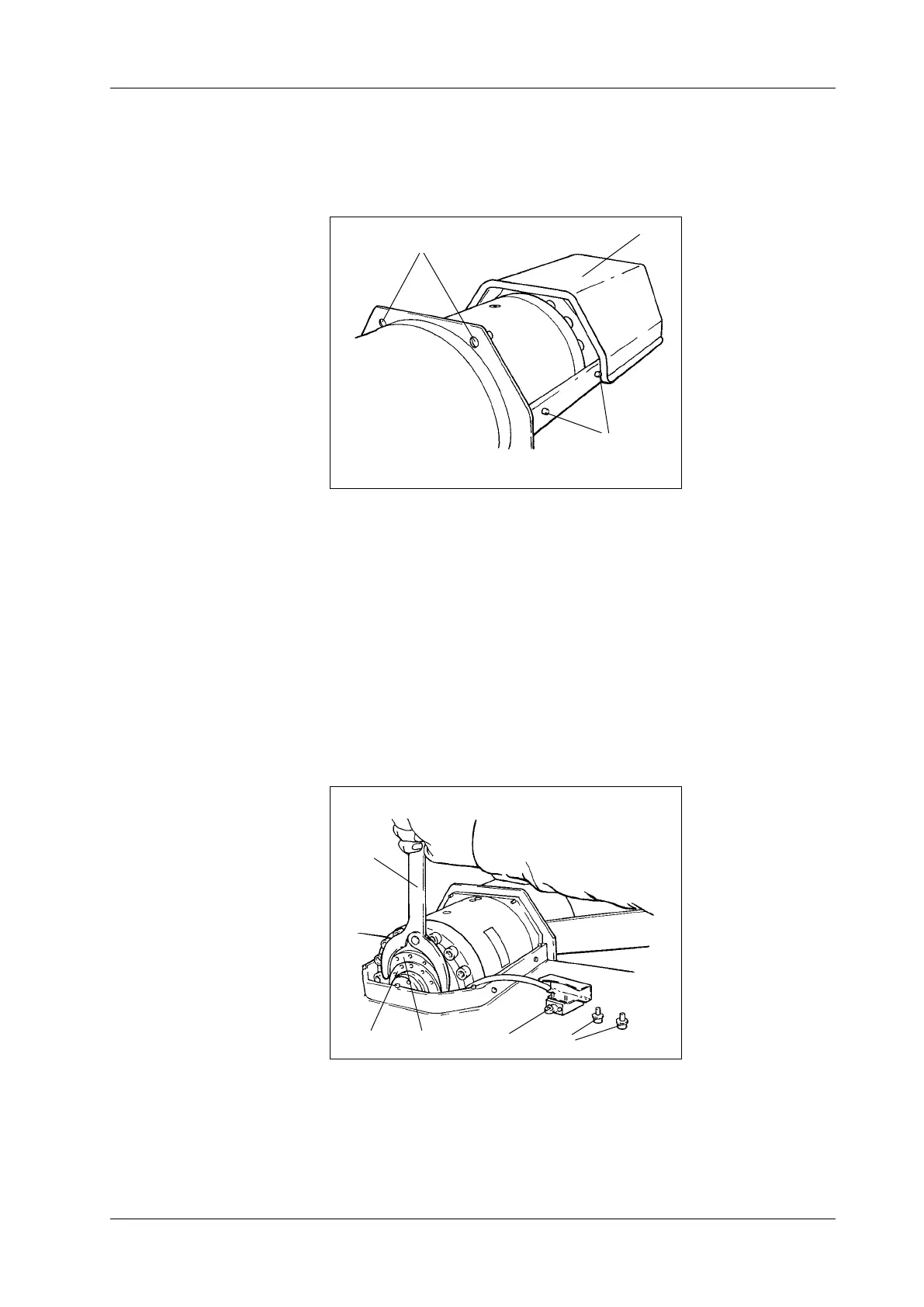
• Undo the two top mounting bolts (1) on the back of drive hood (2) and
tap the bolts to release the drive hood. Push the hood and its seal in
the direction of the operator side until the pins (3) release the guide
grooves and lift it off.
1 Mounting bolts
2 Drive hood
3 Pins
Fig. 3-8
Drive hood
1
3
2
• Undo the mounting screws (1) of switch (2) and put it down on the
machine housing.
• Undo the guard ring (3) with the face spanner (4).
• Use the setting ring (5) to set the desired angle of rotation. One turn of
the setting ring adjusts the angle of rotation by 2.7°. This corresponds
to an adjustment in the height of the trolley hoist of approx. 50 mm.
The gap between the oor and the edge of the trolley guide on the
trolley hoist needs to be approx. 237 mm.
• Turn clockwise: trolley hoist moves up
• Turn anti-clockwise: trolley hoist moves down
1 Mounting screws
2 Switch
3 Guard ring
4 Face spanner
5 Setting ring
Fig. 3-9
Setting trolley hoist
1
3
2
4
5