ROBOT HP7E / HP10E / HP12E / HP15E / HP20E4. Setting up
4-2 © VEMAG 2010
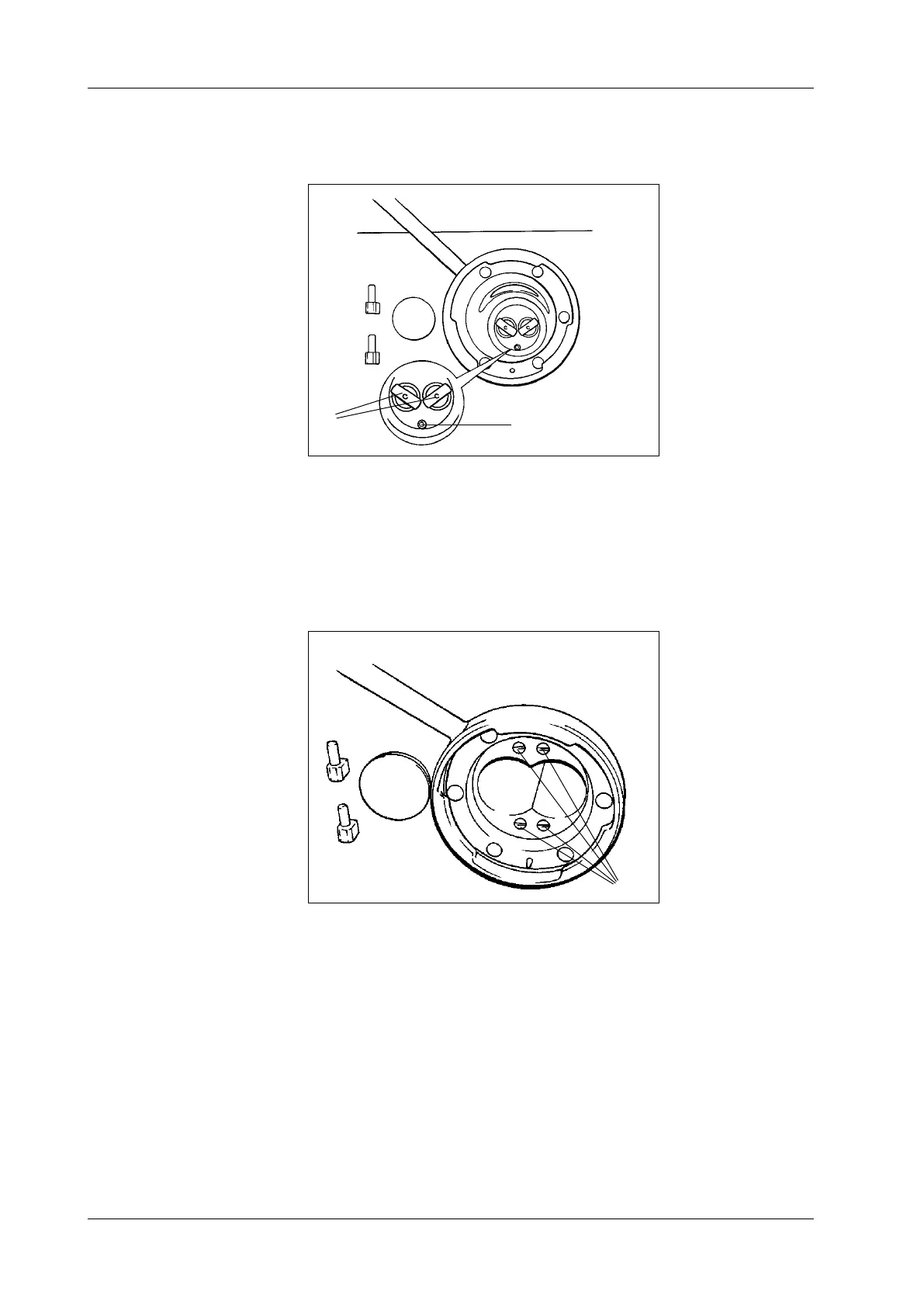
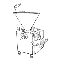
A pin (1) under the coupling pins (2) in the feed cylinder centres the dou-
ble screw housing which has the appropriate bore on its end face.
1 Centring pin
2 Coupling pins
Fig. 4-2
Centring the double screw
housing
1
2
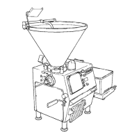
• To prevent air bubbles in the product, the air relief bores of the double
screw housing should be adjusted to suit the product using the setting
screws (1). The air relief bores are closed when the screw slots are
horizontal. If the screw slots are vertical with the screws tightened
right up, the air relief bores are open.
1 Setting screws
Fig. 4-3
Setting the air relief bores
1
• The product weight set should be compared with the weight actually
lled at the start of production.