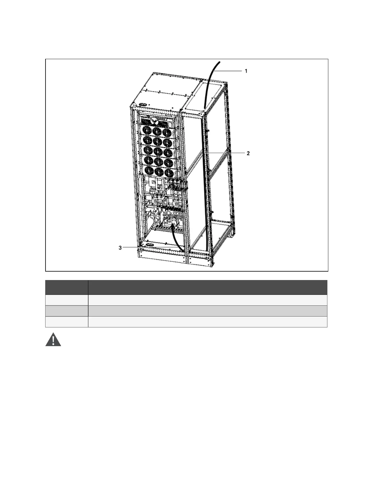
Figure 9.3 Parallel cabinet electrical connection
N o. Descriptio n
1 Remove the top plate, lead cables into the cabinet.
2 Route cables along the cabinet inside, and use cable ties to bind them
3 Remove the bottom plate, connect cables to corresponding terminals
W ARN ING ! B efore cab les connection, m ake sure that all external an d in ternal pow er sw itches
of the U P S are off, and post necessary warning signs to p revent inadvertent operation of the
sw itches. M ean w hile, m easu re the voltages betw een the UPS term inals and the voltages
betw een the term inals and the earth.
N O T E: After connection, take ap propriate m easu res to seal the cable entry holes.
9 Options
145
Vertiv™ Liebert® APM Plus User Manual