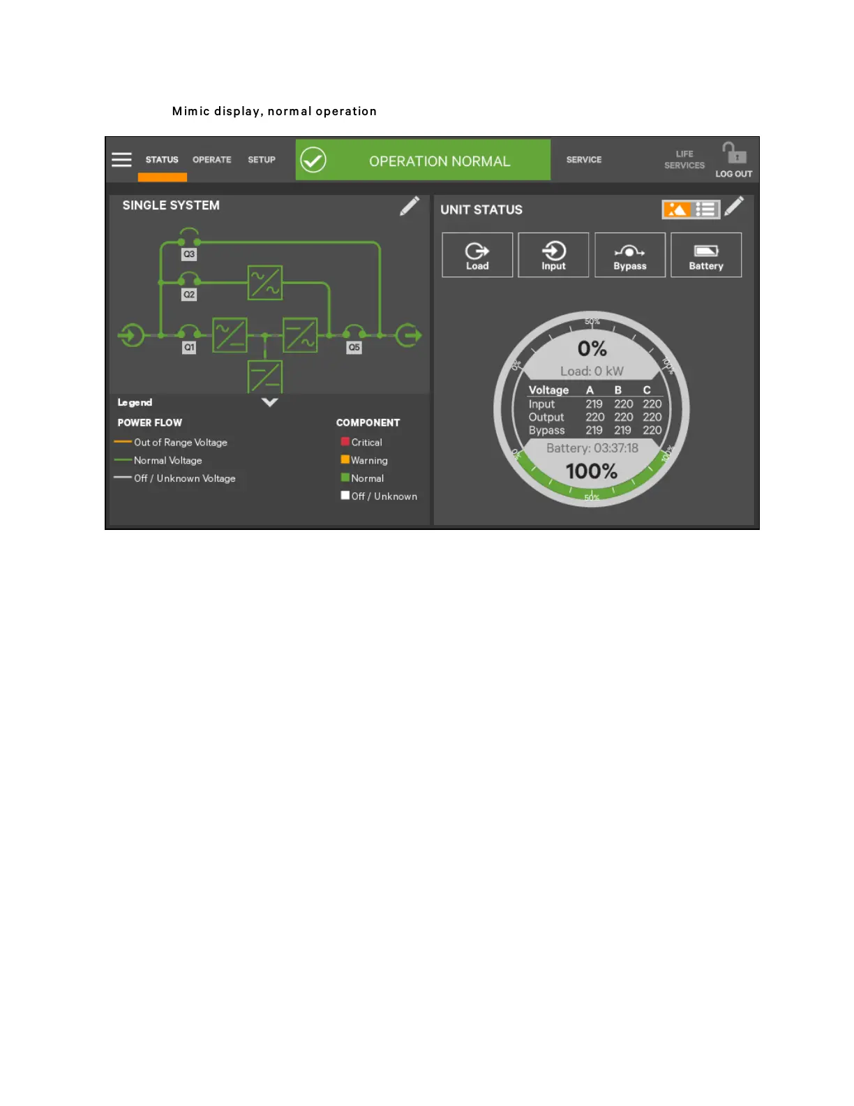
Figure 5.5 M im ic display, n orm al operation
UNIT STATUS Panel Components
The UNIT STATUS panel is identical for all PIN access levels (see Figure 5.6 on the facing page). Observers will not have the
pencil edit icon. In the default graphic view, the UNIT STATUS panel shows:
• Status Gauge-Connected load shown in kW and as a percentage of capacity; input, output, and bypass voltage
for each phase (default data may be changed; see Viewing UPS Data with the Status Gauge).
• Input Detail Icon
• Battery Detail Icon
• Bypass Detail Icon
• Load Detail Icon
• Environmental Detail Icon
Touching any of the detail icons reveals additional data about that selection in the opposite panel. The data panel can be
closed by clicking the Close radio button or by clicking the same or another detail icon. The read-only information is available
to all access levels (see Figure 5.7 on the facing page).
N O T E: If the Status G auge is show ing, no more than four d etail icons will be visib le at a tim e.
Rem oving the S tatus G auge perm its show ing of all five detail icons. Th e view m ay b e custom ized to
show less than four.
5 Operator Control and Display Panel
53
Vertiv™ Liebert® APM Plus User Manual