Chapter 4 Deployment of the CPU 21x-2BT10 with TCP/IP Manual VIPA CPU 21x
4-40 HB103E - Rev. 05/45
There are two options to start the diagnostic tool:
• Via Windows-START menu > SIMATIC ... NCM S7 > Diagnostic
• Within the project engineering res. the hardware configuration via the
register "Diagnostic" in the "Property" dialog with [Execute].
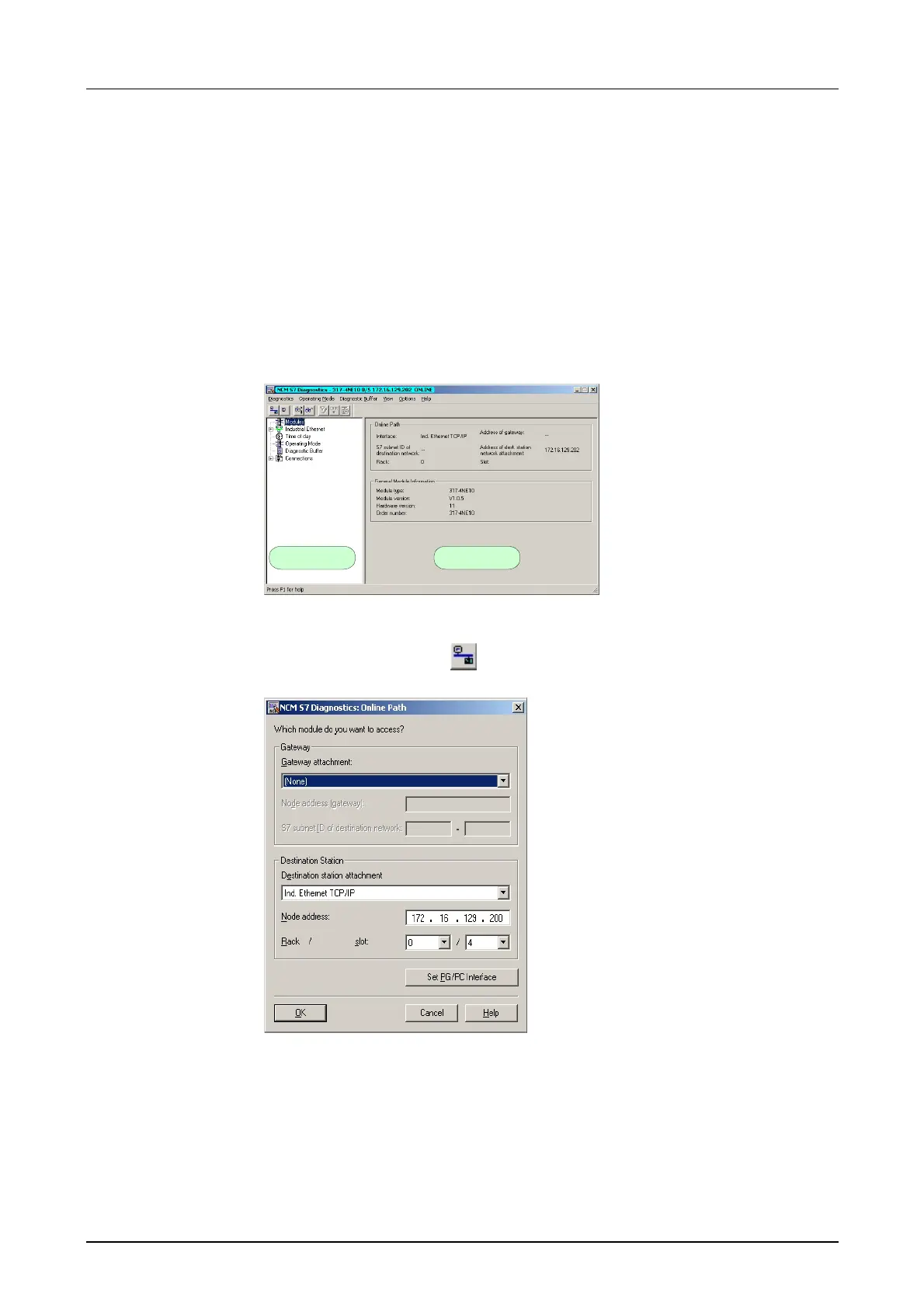
The working surface of the diagnostic tool has the following structure:
The navigation area at the left side contains the hierarchical listed
diagnostic objects. Depending on CP type and configured connections
there is an adjusted object structure in the navigation area.
The information area at the right side always shows the result of the
navigation function you chose in the navigation area.
Navigation area Information area
4
A diagnostic always requires a online connection to the CP you want to
control. For this click on
at the symbol bar. The following dialog window
appears:
Set the following parameters at destination station:
Connection...: Ind. Ethernet TCP/IP
Station addr.: Enter the IP address of the CP
Module rack/slot:
Always choose rack 0 and slot 4 when using System 200V.
Set your PG/PC interface to TCP/IP...RFC1006. [OK] starts the online
diagnostic.
Start NCM
diagnostic
Structure
No diagnostic
without
connection

 Loading...


