Chapter 9 Deployment CPU 21xSER-1 Manual VIPA CPU 21x
9-26 HB103E - Rev. 05/45
The following components are required for the example:
• 1 CPU 21xSER-1 as Modbus RTU master
• 1 System 200V with CP 240 as Modbus RTU slave
• Siemens SIMATIC Manager and options for project transfer
• Modbus cable connection
• Execute the project engineering for the master!
Configure the master like the CP 240 slave (see structure above)!
• Execute the project engineering of the CP 240 slave!
The parameterization of the CP 240 happens via the hardware
configuration. Here you set for the input and output range the start
address from where on the fixed length of 16Byte for in- and output are
stored in the peripheral area of the CPU.
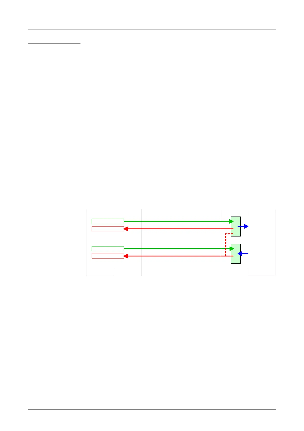
The data transfer via Modbus does not require a PLC application. You
only have to make sure that the data received by the master are
evaluated in the CPU and that the data that is to be transferred to the
master are stored in the output area. This is reached by transferring the
according word of the process image cyclically.
The following picture illustrates this:
CPU 21xSER-1
CPU Master
System 200V
CP 240 CPU
SER_SND
SER_RCV
LPEW
SER_RCV
TPAW
Code/Data
RetVal
SER_SND
Code
Data
zyclical
data transfer
M: CPU 21xSER-1
S: CP 240
Approach

 Loading...


