2-56 Card Slot Programming
Features and Operation
STARPLUS STSe - Programming & Operations Manual August 2005
Related Information
Programming Steps
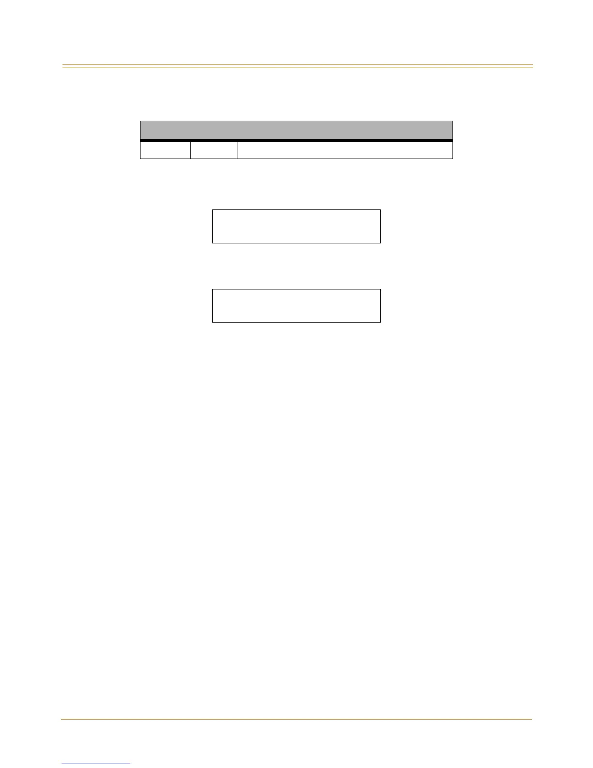
1. Press FLASH and dial [24]. The following message displays on the display:
2. Press the button corresponding to the desired SLOT location. (Buttons #1-14 indicate
peripheral card slots 0-13.)
3. Enter a valid number for the type of card plugged into the current peripheral card slot.
[00] = None [13] = SL04 (represents SLIB w/ 4 ports)
[02] = DTIB [15] = LCI4 (represents LCOBC)
[04] = SL02 (represents SLIB w/ 2 ports) [16] = SI04 (represents SLIBC w/ 4 ports)
[08] = PRIB [17] = VM1B (represents VM Interface Board)
[09] = T1IB
4. If the T1IB option is selected in step 3, then enter a valid number (1-5) to specify the
desired cluster (partial) quantity; otherwise, skip to step 5.
[1] = cluster of 4 [4] = cluster of 16
[2] = cluster of 8 [5] = cluster of 20
[3] = cluster of 12 No Entry = All CO lines
5. Press HOLD to save the entry. A confirmation tone sounds and the display updates.
6. Press the reset button on the Main Board Unit (MBU).
DEFAULT … Slot 0, 1, and 2 are identified as DTIB, LCI4, and SL02 respectively.
Conditions
» After programming card slots, a system reset must be performed.
» If a caller ID card is used in the system, you must use FLASH 40, Page C, Button #2 to set
the Ring Delay Timer to a setting of 05 (sec). This allows sufficient time for receipt of ICLID
information from the telephone company. Refer to “Ring Delay Timer” on page A-9.
Quick Reference
Flash 80 Button #20 System Reset (refer to “System Reset” on page 2-298).
CABINET 0
ENTER BUTTON NUMBER
CAB 0 SLOT XX 00-21
DTIB