Installation procedure, general
D4 or D6 engine, single installation with stern drive DPH/DPR
Locate the electrical equipment far from heat sourc-
es.
Choose cable lengths to minimize the number of con-
nectors and never locate a connection in a non ac-
cessible area.
NOTE! You are not allowed to build network in a way
that branches will be formed. Bus cables with branch-
es longer than 0.5 m (1.6 ft) cannot exist in an EVC
system. Also please refer to the Building a network.
Requirements chapter for more information.
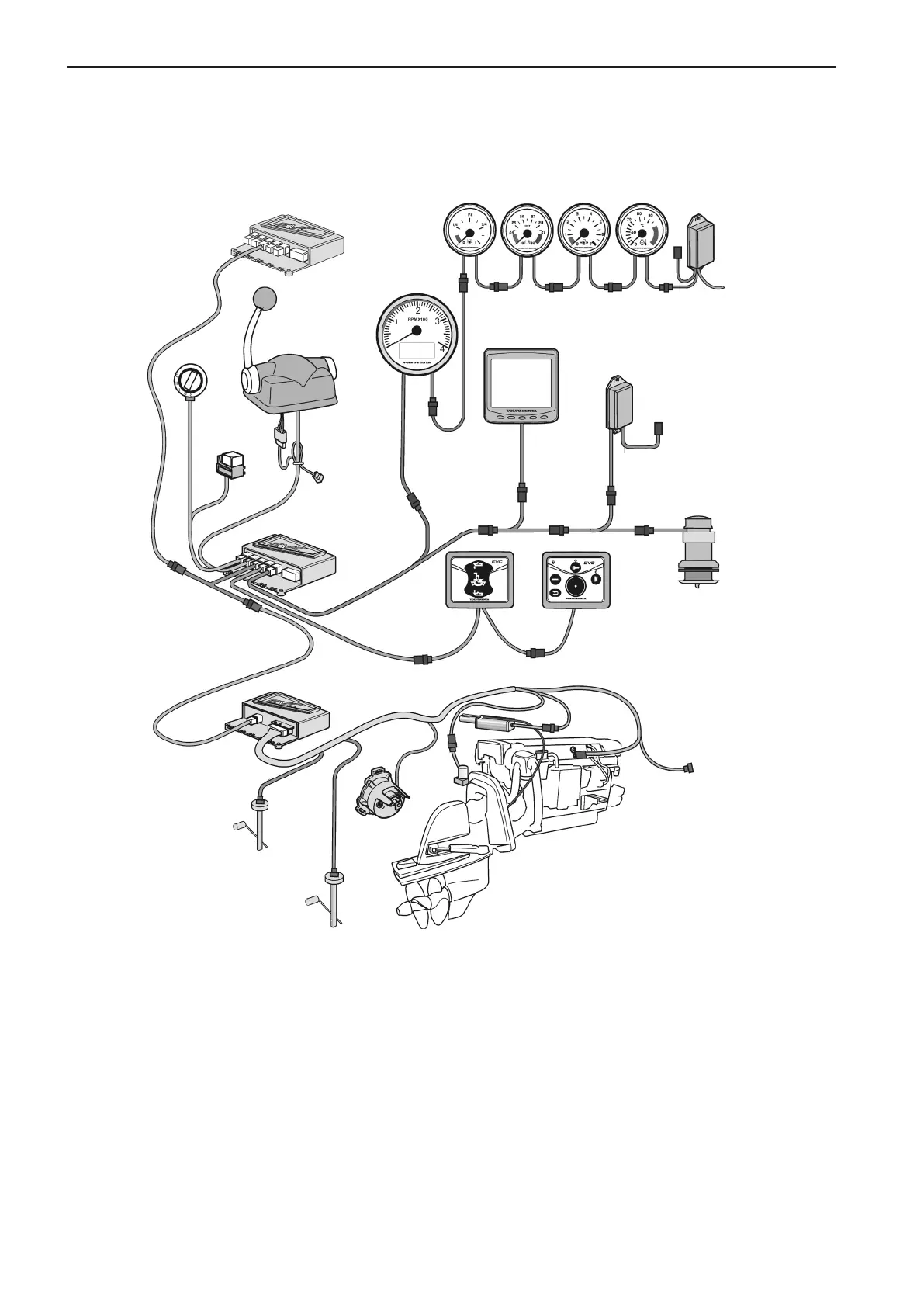
The figures on the following pages show different
EVC installations. The principle is the same for all
combinations of engines, helm stations and controls.
NOTE! The nodes are always located close to the
components they control. A powertrain node, the
Powertrain Control Unit (PCU), is located in the en-
gine room. A helm node, the Helm station Control
Unit (HCU), is located close to the helm station.
Cables and connectors must never be located where
they are exposed to water.
PCU
HCU
To secondary
helm station
Instruments
EVC control
panel
Key
switch
Relay,
external
accessories
Control
Drive DPH/DPR
Fuel level
sender
Diagnostic
connection, 6 pin
HCU
Y-connector
Protection
(Plug)
Powertrim
panel
Engine D4/D6
Water
level
sender
Rudder
indicator
Multilink
breakout
Y-split
Multilink
EVC system
tachometer
Multisensor
NMEA
interface
EVC system
display
Multilink
breakout
Multilink
breakout
Auxiliary
dimmer unit
(ADU)
28