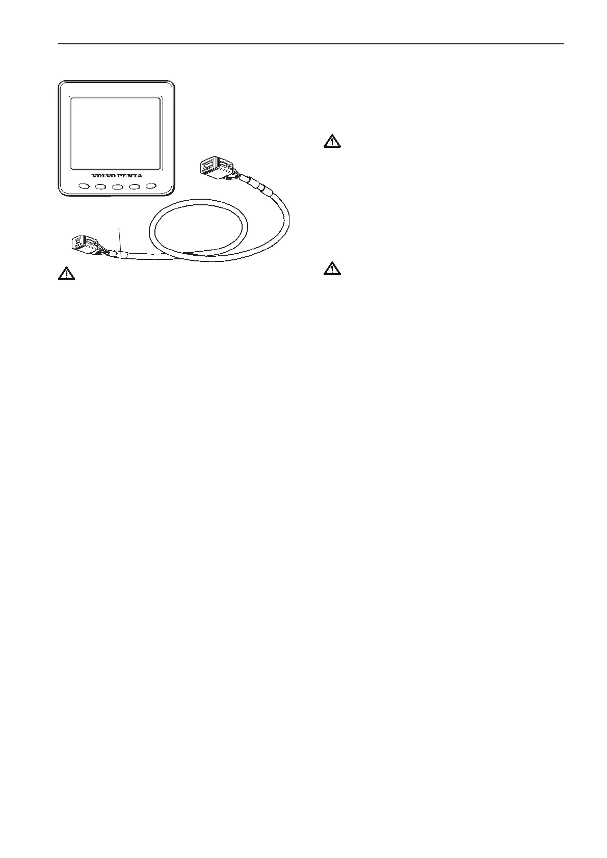
EVC system display
IMPORTANT! An EVC system display can be
connected together with a tachometer. The dis-
play can also substitute a tachometer. The EVC-
C system must have either a tachometer or a
display.
The following information is available in the
EVC-C system display:
- Coolant pressure
- Fuel pressure
- Fuel level
- Engine oil pressure
- Turbo pressure
- Coolant temperature
- Transmission oil pressure
- Voltage
- Exhaust temperature
- Engine oil temperature
- Transmission oil temperature
- Engine rpm
- Engine running hours
- Boat speed
- Engine Powertrim
- Sea water pressure
- Trip data: (fuel rate, fuel consumption, fuel con-
sumption/time, trip fuel consumption, trip fuel
consumption/time, remaining fuel, trip hours, trip
distance, remaining distance to empty tank, re-
maining time until tank is empty)
- Sea water depth
- Sea water depth alarm
- Sea water temperature
- Rudder angle
- Engine oil filter differential pressure
Information is depending on engine model, number of
sensors and type of accessories.
The EVC display kit consists of the display with con-
nection and a cable, length 1.5 m (5 ft) with 12- and
6- pin connections. An extension cable may be used,
lengths: 1.5, 3, 5, 7, 9, 11 m (5, 10, 16, 23, 30, 36 ft).
Please refer to the Connection section on the next
pages.
IMPORTANT! Always connect instruments and
senders which are common for both engines,
such as speedometer, rudder indicator etc to
port HCU. The port engine is the master engine
in the EVC system.
NOTE! In a twin installation the default setting of the
display will show port engine data. Please refer to
the EVC system display/Calibration and settings
chapter for further information.
IMPORTANT! In a twin installation, when using
one combined EVC system display, the display
must be configured as a “TWIN” before auto con-
figuration is performed.
In a twin installation, when using two EVC sys-
tem displays, the displays must be configured as
“PORT” resp. “STARBOARD” before auto con-
figuration is performed.
NOTE! The EVC-C system allows maximum one dis-
play connected to each HCU.
Location and fitting
NOTE! Allow adequate clearance behind the display
for cable connection to ensure that the cable is not
unduly stressed. Also ensure that there is sufficient
length of cable to remove the unit for servicing pur-
poses.
The instrument is usually installed on a dash board. It
can be mounted from above or flush from under the
dash board. Flush mounting demands tailor made
fittings. Templates are included. Please refer to the
Templates for controls and panels chapter.
NOTE! Cut out dimensions are nominal only and
should be checked against physical units prior to ma-
chining.
X5 MULTILINK
Yellow
DISPLAY
CONN.
Part No.
63
EVC-C Installation procedure, helm