Y-connector, location
The Y-connnector is used to form a branch in the
EVC standard bus cable when there are several helm
stations (HCUs) in the system. Also please refer to
the Building a network, requirements chapter.
IMPORTANT! The Y-connector must always be
connected directly to the PCU (X2) or the HCU
(X2) without using any extension cables.
Key switch and relay for
external accessories
IMPORTANT! There must always be one key
switch to operate each engine. The key switch
shall be connected to the main helm station.
On additional helm stations start/stop panels
should be used.
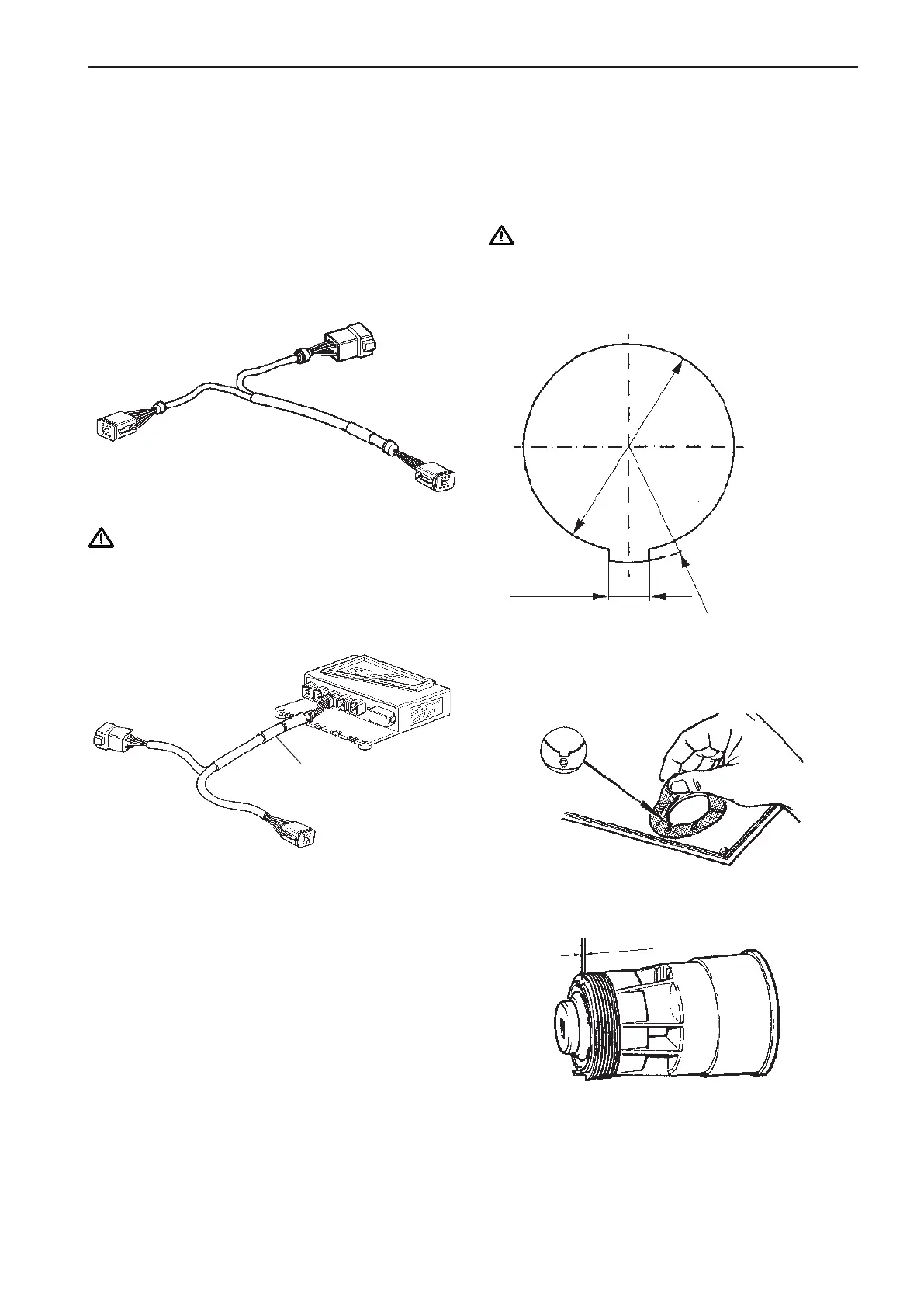
Locate a dry, suitable place for the switch and make
a hole according to the drawing.
Fix the adhesive label.
The switch fits to 2 mm (0,08”) panel. If the switch
is installed in a thicker panel the switch housing can
be trimmed by up to 10 mm (0,4”), 1 mm (0,04”) bet-
ween each flute.
Figure shows the Y-connector fitted to a HCU unit.
Installation procedure, helm
Part No.
Part No.
Y-connector
∅=32.1 mm (1.26")
6.0 mm (0.24")
R=18 mm (0.71")
1 mm (0.04")
49