Building an EVC network
Requirements
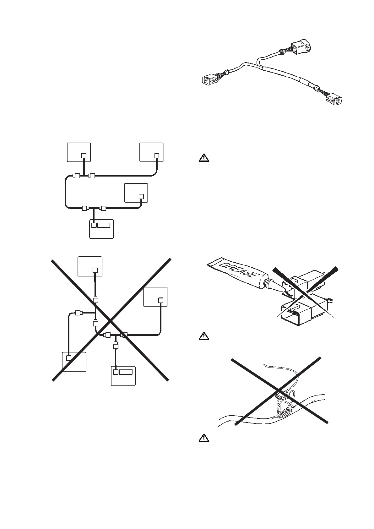
The EVC system is a distributed system with the
electronic units (nodes) located all around the boat.
The EVC nodes are the Powertrain Control Unit
(PCU) located in the engine room and the Helm
Control Unit (HCU) located near the helm station.
The standard bus cable connects the nodes to each
other and forms a network. The standard bus cable,
Y-connectors and extension cables are used for this
purpose.
The nodes must be conneced and the network must
be designed in such a way that no branches will be
formed. Longer branches (max. 0.5 m/1.6 ft) may
generate communication disturbances in the EVC
bus cable.
Figure A above illustrates a correctly designed net-
work including three helm stations. Figure B gives an
example of an incorrect network with long branches.
Fig. B
PCU
HCU
HCU
HCU
This is avoided by always connecting the longer
cable on the Y-connector directly to the node (PCU
or HCU) without using any extension cable.
IMPORTANT! Note that the Y-connector always
is connected directly to a node without use of
any extension cable.
Important
Part No.
Connection to
PCU or HCU
IMPORTANT! Never use any kind of grease in
the EVC connectors.
IMPORTANT! Never cut or modifiy the Volvo
Penta EVC cable harnesses. For extra power
supply use the Volvo Penta relay for accessories.
Refer to the Relay for external accessories
section.
Fig. A
PCU
HCU
HCU
HCU
33
EVC-C Installation procedure, general