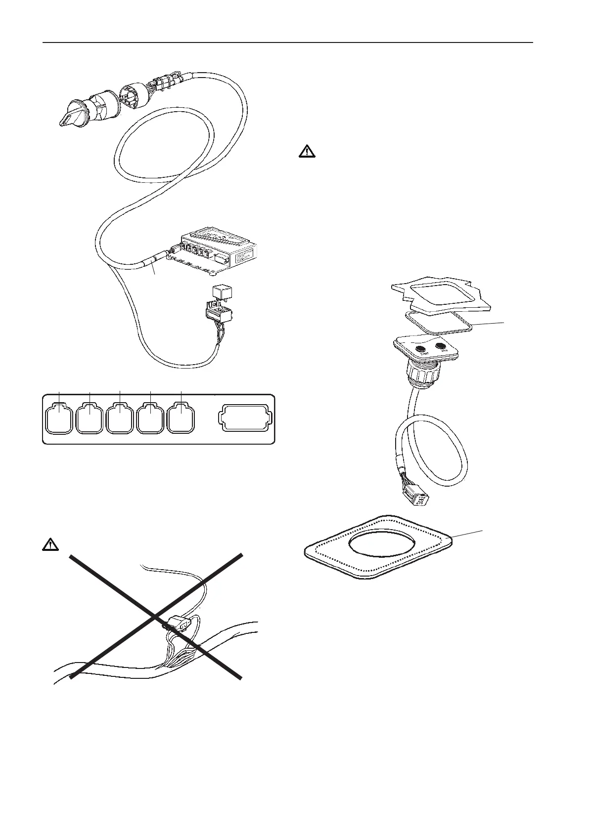
Connection to the HCU
The key switch is connected to the HCU, X4:KEY
connection (gray) togheter with the relay socket for
external accessories.
Make a hole for the button panel using the template
enclosed with the installation kits. Also refer to the
Templates for controls and panels chapter.
The insert depth is 4 mm (0.16") including gasket.
Separate the outher part of the gasket (1) from the
inner part. Remove the protective paper and fit the
gasket (2) in the panel recess.
Install the panel as illustrated in the figure.
NOTE! It is important that the self adhesive gasket is
fitted properly in the panel recess.
Start/stop panel
Use templates enclosed in the mounting kits. Please
refer to the Templates for controls and panels
chapter.
NOTE! There are start/stop panels suitable for single
and twin installations.
IMPORTANT! For twin installations, it is es-
sential to distinguish between the Red and the
Green connections. Red is for port engine and
Green is for starboard engine.
The port engine is the master engine.
Flush-mounted panel
Single engine panel is shown.
Never cut or modifiy the Volvo Penta EVC cable har-
nesses. For extra power supply use the Volvo Penta
relay for accessories.
Refer to the Relay for external accessories section.
IMPORTANT!
1
1
CONN X4
Gray
Relay for
external
accessories
START/
STOP KEY
X5:MULTILINKX2:DATALINK X3:AUX
X4:KEY
Green YellowPink
Gray
Blue
X7:CONTROLS
X8:NOT USED
50
Installation procedure, helm EVC-C