Multisensor
For a complete description of installation work and
testing, please refer to User and installation in-
structions enclosed in the multisensor kit package.
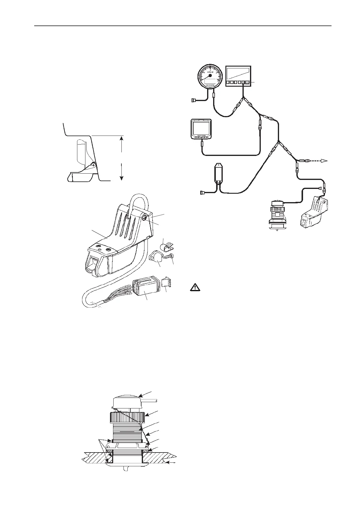
Transom mounted sensor
Hull mounted sensor
Connection to the EVC system
Required
clearance:
130 mm
(5-1/8”)
Clearance
1 Sensor
2 Bracket
3 Shim (9°)
4 Cable cover
5 Clamp
6 Nut
7 Screw
8 Screw, selftapping
9 Screw, selftapping
10 6-pin connector
11 Connector wedge
6, 7
5
9
3
1, 2, 8
4
11
10
1 Hull
2 Hull nut
3 Washer
4 Housing
5 Cap nut
6 Insert
7 Marine sealant
8 Safety wire
6
8
3
5
4
2
7
1
Multisensors are connected to the X5 MULTILINK
connector, directly or via the Y-split, MULTILINK
BREAKOUT cable (yellow PVC coating).
IMPORTANT! Always connect instruments and
senders which are common for both engines,
such as speedometer, rudder indicator, etc to
port HCU. The port engine is the master engine
in the EVC system.
NOTE! If a multisensor and an NMEA interface is
installed only the "Speed over ground" will be pre-
sented in the speedometer and the EVC display.
Calibration of boat speed
Please refer to chapter Calibration and settings,
EVC display.
HCU
port
X5 MULTILINK
(yellow)
Y-split
Sync. con-
nection
Multisensor,
hull mounted
Multisensor, tran-
som mounted
MULTILINK
MULTILINK
BREAKOUT
MULTILINK
NMEA
0183/2000
MULTILINK
Y-split
Y-split
MULTILINK
BREAKOUT
MULTILINK
BREAKOUT
MULTILINK
EVC System
Tachometer
EVC System
Display
71
EVC-C Installation procedure, helm