Input interface, 4–20 mA
Input interface to aftermarket control systems that
support 4–20 mA. No calibration is needed. The fol-
lowing functions are available.
NOTE! The slip and reverse functions must not be
connected if only throttle control is required.
- Throttle function
- Slip function
- Reverse gear
Installation order (Interface In)
NOTE! The interface works at different speeds/baud
rates, depending on whether it is used as an in or out
interface.
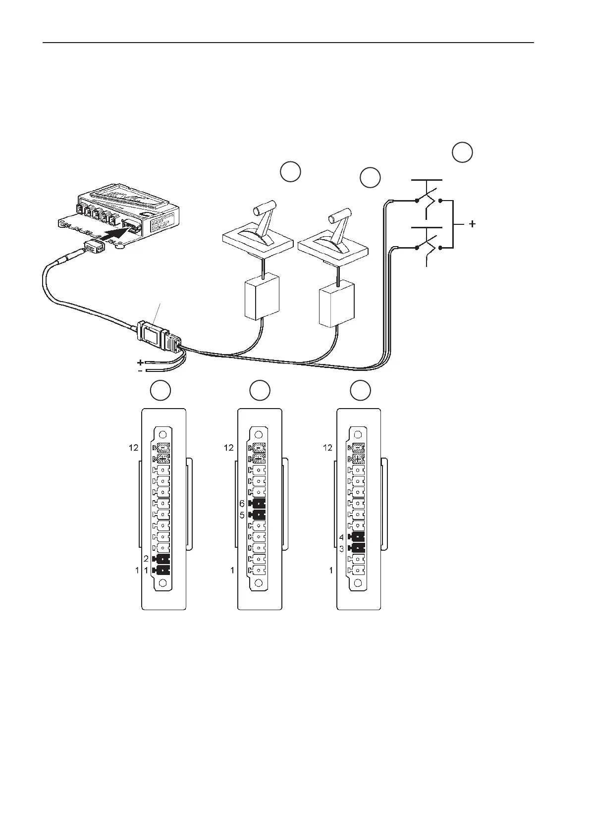
Activate the ”Lever type” parameter in the HCU, using
VODIA.
Connect the control cables to the screw terminal on
the interface (1) as in the table and figure.
NOTE! The specified input signal levels are required
for the interface to work correctly.
Install the accompanying strain relief.
Connect the interface to the 12-pin connector on the
HCU, as in the figure.
NOTE! Fix the interface in a suitable place, using a
tie wrap or screw.
Do an auto configuration of the system. Please refer
to the EVC-C installation manual for more informa-
tion.
1 2 3
1
2
3
FWD
REV
Slip
Throttle
1
HCU
Batt. supply
10-28
VDC
10-28
VDC
4-20 mA
4-20 mA
80
Installation procedure, helm EVC-C