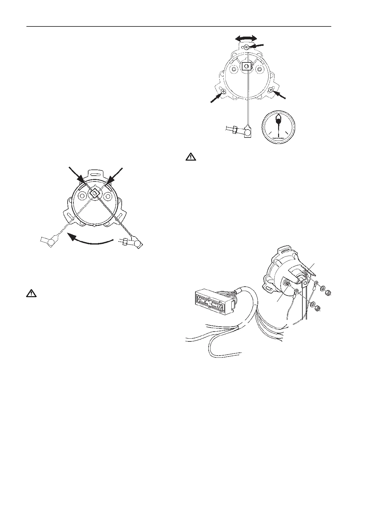
A
Negative
(–)
RUDDER ANGLE
SENDER (GREEN)
R/GN = Signal
SB = Reference
Port side
Rudder indicator
Working area 3–180 ohms.
NOTE! The control rod in this kit is designed for
general installations. In another type of installation,
an alternative control rod version may have to be
used.
Fitting of sensor
NOTE! Always connect the rudder indicator to port
driveline.
Install the bracket for the control rod.
Install the nuts and the ball cups on the control rod.
Remove the existing lever on the sensor. Install the
new lever with the existing screw.
IMPORTANT! Adjust the lever length so that the
sensor shows exactly full mechanical extension
to starboard and port when the rudder does the
same.
Install the control rod between the ball joints on the
bracket and the lever. Lock it with the nuts.
Mark and drill holes for the sensor where it will be
placed. Use the full size template located inside the
back cover of the manual.
IMPORTANT Position the sensor so that the
sensor shows exactly full mechanical extension
to both starboard and port when the rudder does
the same.
Install the sensor with washers and screws without
fully tightening the screws. The sensor position can
be adjusted when cables have been connected to the
sensor and the system is powered up.
Connecting cables to sensor
Extend cables from the cable harness and con-
nect as shown. Red/green cable is connected to pin
marked A and black cable is connected to pin marked
– (negative). Cables are not included in the kit.
Adjusting sensor
Set the rudder fore-and-aft. Turn on the main circuit
breaker. Adjust the sensor position by turning it so
that the rudder indicator (the instrument) shows the
rudder fore-and-aft. Tighten the screws in the sen-
sor. Perform additional checks by turning the steering
wheel to full extension to starboard and port.
46
Installation procedure, engine room EVC-C