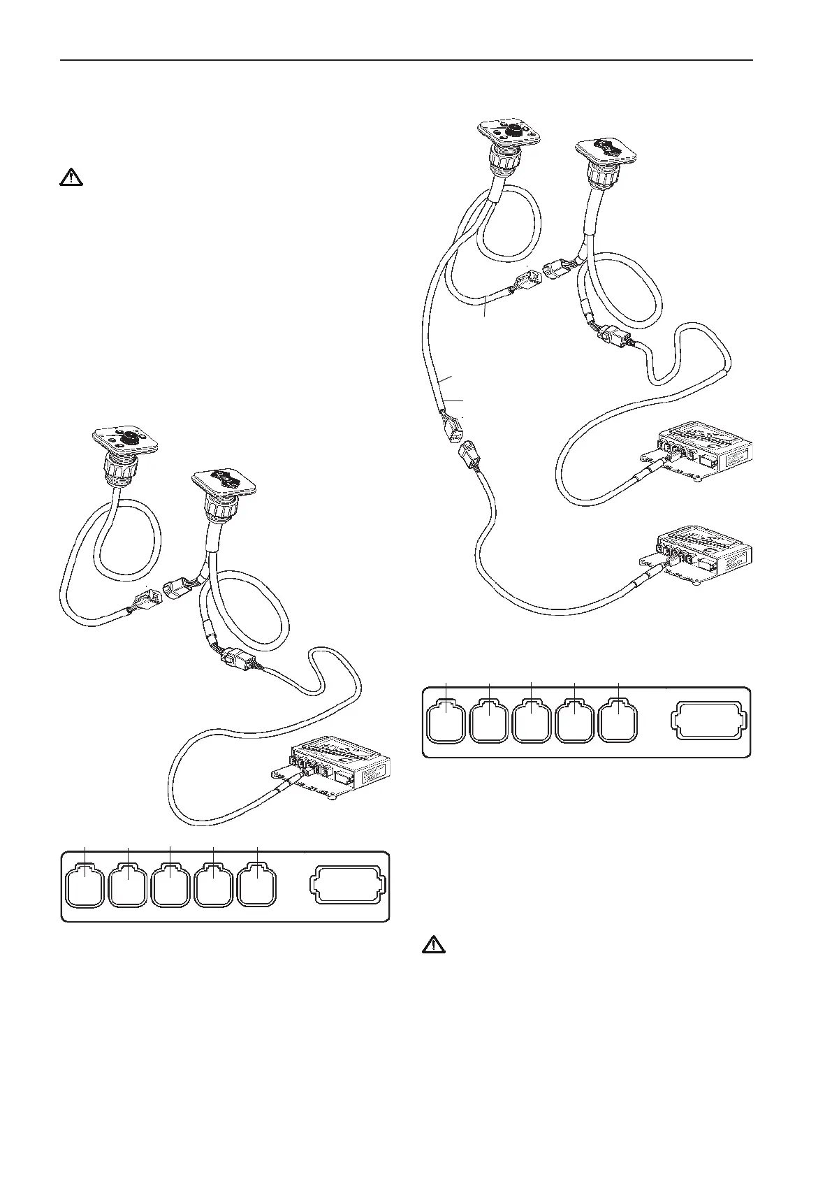
Powertrim panel
Connection of the EVC control
panel and the Powertrim panel
IMPORTANT! In a twin installation the Powertrim
panel must be connected to the HCU for the
port engine. The port engine is always the mas-
ter engine in the EVC system.
NOTE! The Powertrim panel controls both port and
starboard drive in a twin installation.
NOTE! For Powertrim switch on side mounted con-
trols, please refer to the Controls, electronic sec-
tion.
Single engine
Connect the EVC control panel cable marked CONN
X3 to the Powertrim panel.
The Powertrim panel and instrument cable harness
in turn, is connected to in the HCU, X3:AUX (pink).
Connect the red colored cable to the Powertrim pa-
nel, port HCU.
The green colored cable is connected to the con-
nector marked AUXILIARY BUS on the instrument
cable harnesses on the starboard HCU.
The instrument cable harnesses in turn, are connec-
ted to X3:AUX (pink) in the HCUs.
IMPORTANT! Green cable to starboard HCU
and red cable to port HCU.
In a twin installation the Powertrim panel must
be connected to the cable harness from the port
engine HCU.
Twin engine
Starboard
engine
Port
engine
CONN X3
Pink
CONN X3
Pink
Green
marking
strip
Red
marking
strip
AUX.
BUS
AUX.
BUS
Extension
cable
Extension
cable
CONN X3
Pink
AUX. BUS
Extension
cable
X5:MULTILINKX2:DATALINK X3:AUX
X4:KEY
Green Yellow
Pink
Gray Blue
X7:CONTROLS
X8:NOT USED
X5:MULTILINKX2:DATALINK X3:AUX
X4:KEY
Green Yellow
Pink
Gray Blue
X7:CONTROLS
X8:NOT USED
54
Installation procedure, helm EVC-C