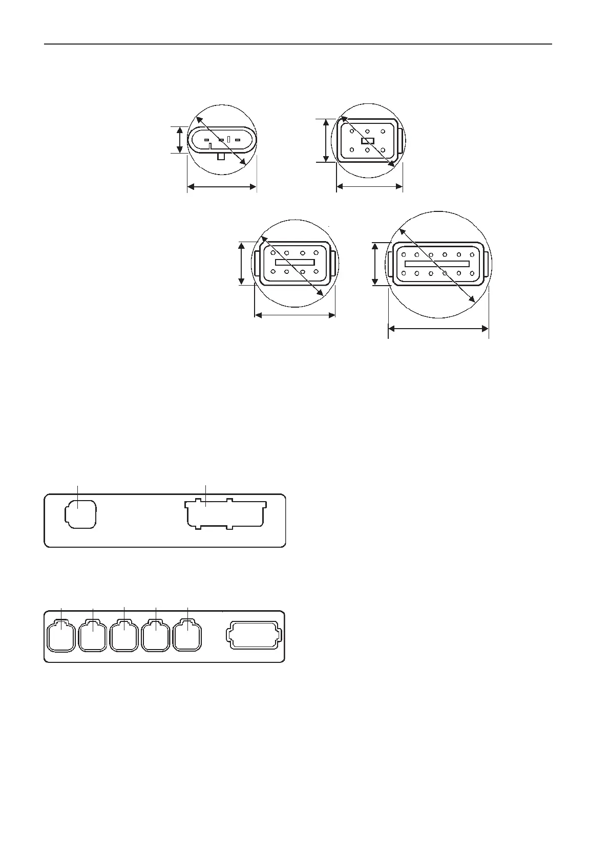
Connector dimensions:
Connector dimensions are given to facilitate making
of lead-throughs in bulk heads etc.
3-pin
H = 18 mm (0.71 in.)
W = 26 mm (1.02 in.)
D = 26 mm (1.02 in.)
6-pin
H = 21 mm (0.82 in.)
W = 23 mm (0.88 in.)
D = 32 mm (1.26 in.)
8-pin
H = 25 mm (0.99 in.)
W = 37 mm (1.44 in.)
D = 45 mm (1.77 in.)
12-pin
H = 23 mm (0.88 in.)
W = 41 mm (1.62 in.)
D = 48 mm (1.90 in.)
Marking and
color coding of cables
All cable connectors are marked and color coded,
to facilitate installation. The markings on cables con-
nected to the PCU and the HCU, correspond with
the designation of connectors and color codes on the
labels on the control units.
NOTE! HCUs with connector X8 open and marked
X8: STEERING cannot be used in an Aquamatic or
inboard systems (only for IPS systems).
HCU label
PCU label
Twin installations, starboard and port
engine
The EVC connectors and the Powertrim panel con-
nectors are color coded with red (port) and green
(starboard) stripes to ensure connections to the right
engine.
The EVC standard bus cable is marked with both
red and green stripes and the color (stripe) not used
should be removed.
NOTE! In a twin installation it is recommended to
mark all cables with red and green stripes during in-
stallation.
Green
Pink
X2:DATALINK X3:ENGINE
H
W
D
12-pin
H
W
D
8-pin
H
W
D
6-pin
W
H
D
3-pin
X5:MULTILINKX2:DATALINK X3:AUX
X4:KEY
Green YellowPink
Gray Blue
X7:CONTROLS
X8:NOT USED
32
Installation procedure, general EVC-C