Relay for external
accessories
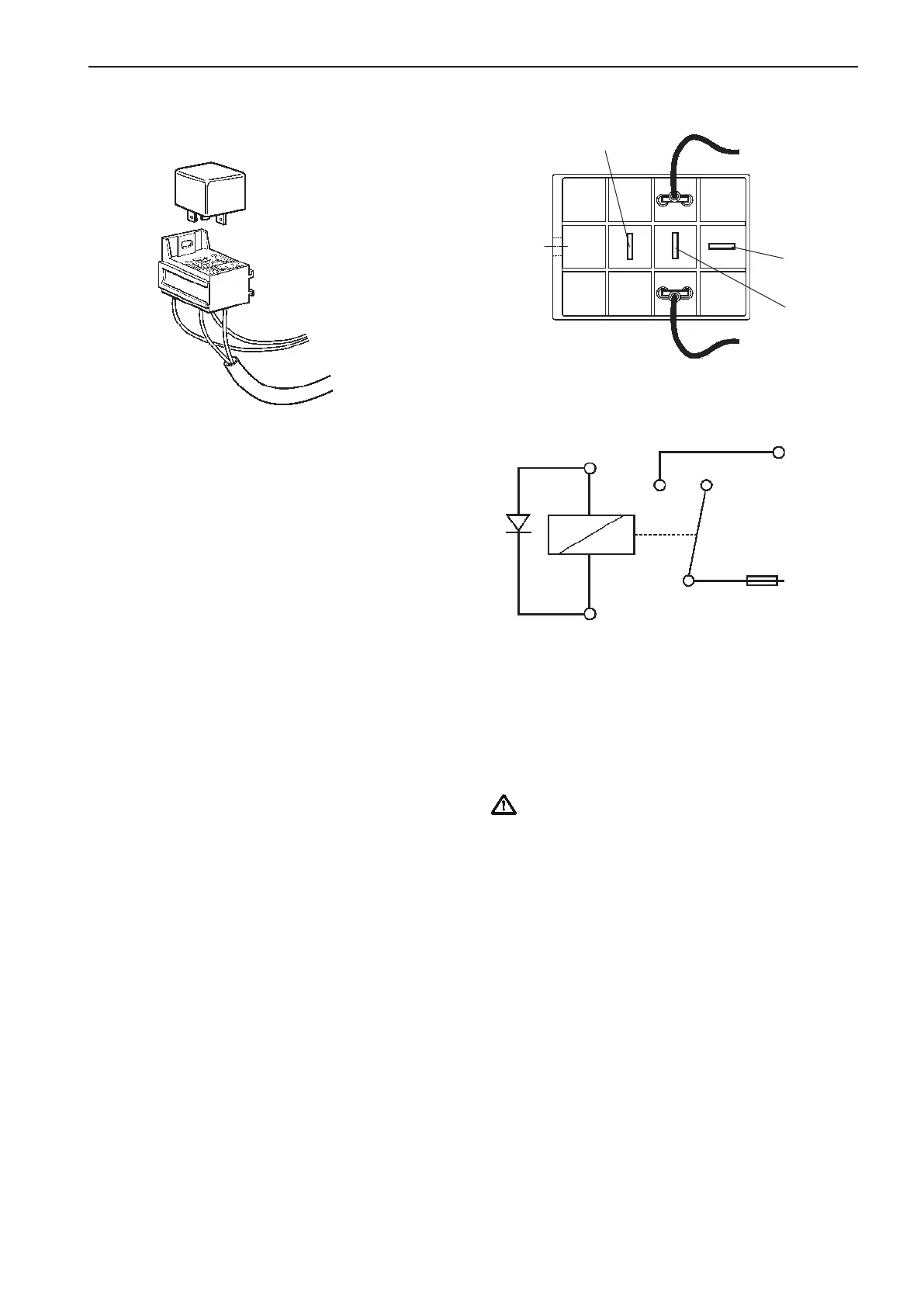
Relay diagram
Connection points on relay socket
Connection 85 and +86 are wired from the EVC cable
harness.
Figure shows the key switch in OFF position and the
relay in open position.
Connect power supply for external accessories from
the battery to connector 30 on the relay socket.
IMPORTANT! Never supply any external ac-
cessories from the EVC system. Always use the
relay.
Connect external accessories to pin 87 which will
supply power when the key switch is ON.
Cables from battery to relay and from relay to ac-
cessories must be dimensioned for the expected
maximum current. There must also be a fuse in the
circuit between battery and relay, preferably close to
the battery.
Maximum current through the relay is 20 Amp.
Maximum output is:
12 V 240 W
24 V 480 W
The relay controls the power supply to external ac-
cessories. The relay position (open or closed) and the
power supply depend on the key switch position. The
relay is normally open and there is no power when
key switch is in the OFF position.
The relay cable and the relay can also be fitted to
a secondary helm station with a start/stop control
panel. In such an installation the relay is activated by
the key switch on the main helm station.
NOTE! All relays in a drive line, and in an active or
inactive helm station are operated by the key switch.
85 SB
+ 86 R
87
87a
30
Power to
accessories
+ 86
85
87 87a
30
Battery
supply (+)
Fuse
Relay
socket
Relay
12V, 20A (D4/D6/D9)
24V, 20A (D6/D9/D12/D16)
Power to accessories
Battery supply
Cable
harness
55
EVC-C Installation procedure, helm
 Loading...