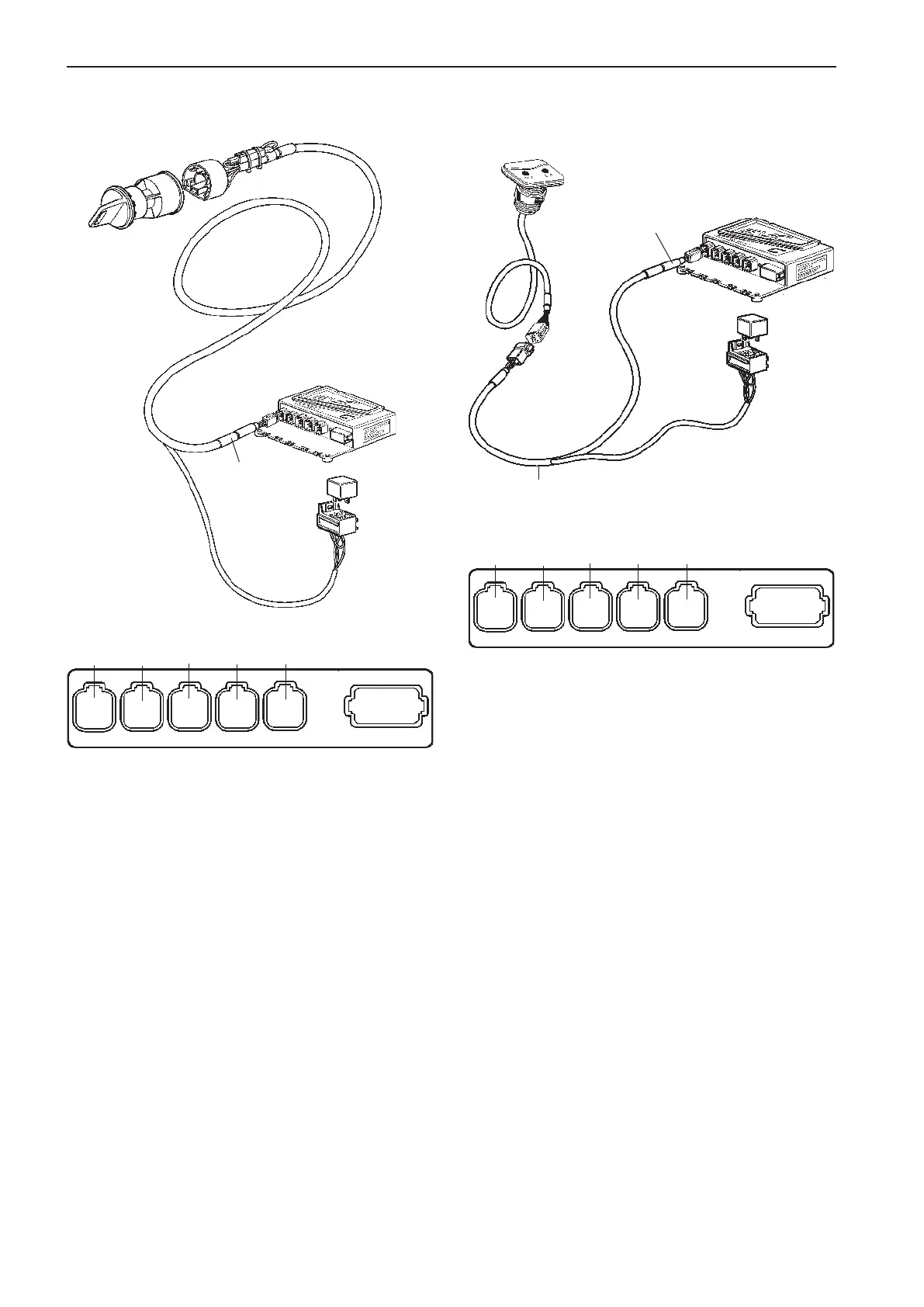
Connection to the HCU
when using a key switch
Connection to the HCU
when using a start/stop panel
The relay socket is permanently connected to the
cable for the key switch. The key switch cable is con-
nected to the HCU, X4:KEY connection (gray).
The start/stop panel is connected to the HCU, X4:
KEY (gray) or to separate relay cable harness (op-
tion).
The cable harness is option. The connector on the
harness is marked KEY and the harness is connec-
ted to the HCU, X4:KEY connection (gray).
CONN X4
Gray
Relay for
external
accessories
CONN X4
Gray
KEY
Relay cable
(option)
X5:MULTILINKX2:DATALINK X3:AUX
X4:KEY
Green YellowPink
Gray
Blue
X7:CONTROLS
X8:NOT USED
X5:MULTILINKX2:DATALINK X3:AUX
X4:KEY
Green YellowPink
Gray
Blue
X7:CONTROLS
X8:NOT USED
56
Installation procedure, helm EVC-C
 Loading...