The wiring is first routed to the PCU unit. Each en-
gine is connected to the EVC system via its own PCU
unit.
Connections in the engine room should be positioned
above the level of the alternator .
Avoid connections hidden behind fixed panels etc.
For item figures, please refer to page 31.
To obtain a clear overview, begin by determining the
location of the main components.
All cables have colored marking sleeves and sleeves
with an identity printed on them.
Begin at the engine room and build the system to-
wards the main helm station. Then continue with the
other helm stations.
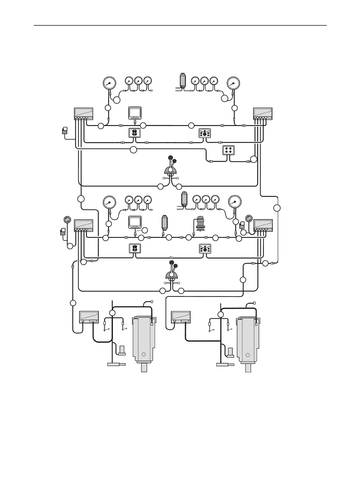
Cable routing
D4 and D6 . Twin engine installation, main and secondary helm stations.
Stern drive DPH/DPR installation is shown.
Main
station
Secondary
station
HCU
Engine,
port
Engine,
stb
HCU
HCU
PCU
Relay
Key
switch
Start/stop
panel
EVC
system
display
EVC
control
panel
Powertrim
panel
Power
Trim
pump
Actuator
Instruments
Controls
Controls
Fuel
level
sender
PCU
HCU
Rudder
indicator
Gear pot.
switches
not used
Diagnosis
(VODIA)
Fresh
water
level
sender
Not used
EVC system
tachometer
Instruments
1a
2
4
8a
EVC
control
panel
Powertrim
panel
7
8
2
4
6
3
11
Multi-
sensor
Actuator
NMEA
ADU
ADU
4
6
5
6
6
12
6
8
3
11
1a
Key
switch
4
7
11
44
7
7
6
Drive
DPH/DPR
Drive
DPH/DPR
Instruments
Relay
Fuel
level
sender
Fresh
water
level
Gear pot.
switches
not used
12
EVC
system
display
EVC system
tachometer
EVC system
tachometer
EVC system
tachometer
4
29
EVC-C Installation procedure, general