Connect the black (fuel level sender) or blue (water
level sender) cable to the terminal marked ⊥ (earth/
ground) and the green/black or blue/black cable to
the other terminal.
NOTE! On the Fuel/Water level sender cables a bat-
tery minus/ground cable must be connected to the
reference line (black or blue). This cable is not includ-
ed in the cable harness.
Setting of low fuel alarm
Setting (on/off) of the fuel alarm is made via the
EVC system tachometer/display and the EVC control
panel. Please refer to the Calibration and settings
section in this manual.
NOTE! The default level of the fuel alarm is set to 0%
of the tank volume, which means that the alarm is
off. For the alarm to function, the desired alarm level
must be set.
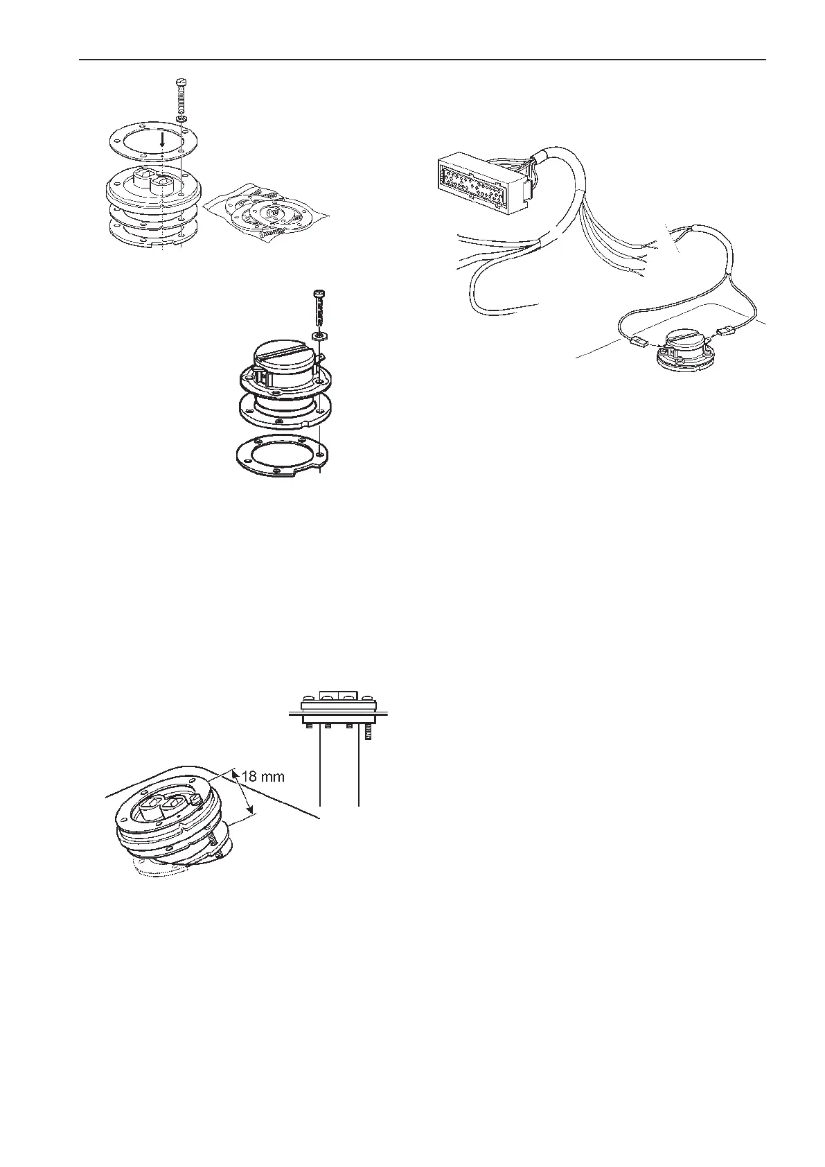
outside the tank. Align the sensor so that the float
has free movement inside the tank. Tighten the long
screw so that the seals and the ring with the tapped
holes come into place.
Install the remaining screws and tighten all of them
simultaneously.
The level sender cables are connected to the EVC
system via the engine–PCU cable harness.
Assemble the ring with the tapped holes and rub-
ber seals with the long screw. Note the locations of
the cutout on the ring with the tapped holes, and the
marks on the upper ring and rubber seals. Make sure
that there is the greatest possible distance between
the seal and the ring with the tapped holes.
Lower the sensor with float and the ring with tapped
holes down into the tank. The rubber seal must be
FUEL LEVEL
SENDER (black)
GN/SB = Signal
SB = Reference
WATER LEVEL
SENDER (blue)
BL/SB = Signal
SB = Reference
Fresh water level sender
Fuel level sender
45
EVC-C Installation procedure, engine room
 Loading...