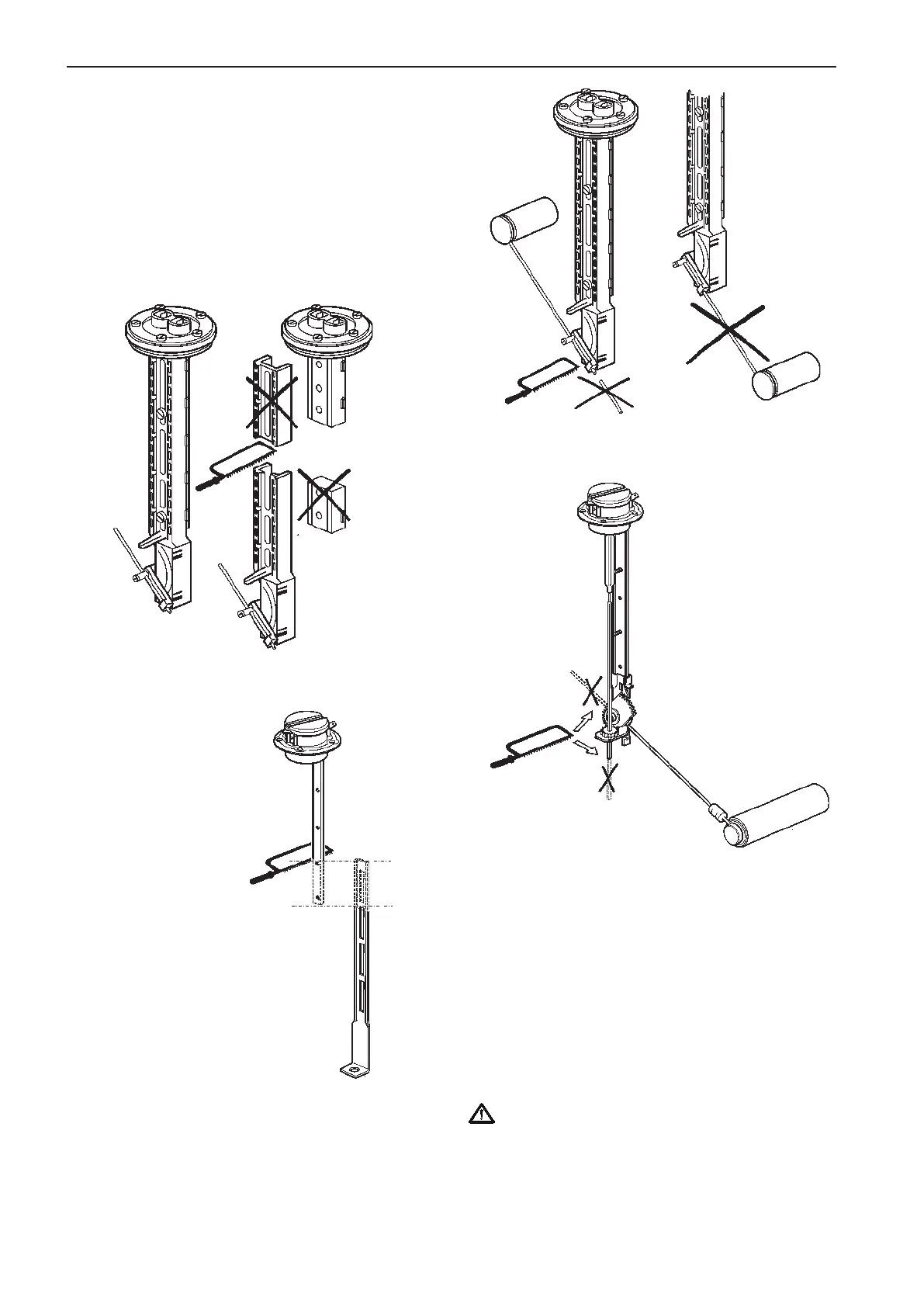
Fuel level sender
Fresh water level sender
Install the float as in figure. Calculate and adjust the
length of the float arm using the formula:
R=H/1.64-18 mm and also on the basis of the mini-
mum and maximum fuel levels.
Example: H=580 mm (H/2=290 mm)
R=580/1.64-18
R=353-18
R=336 mm
Tighten the screw and cut off the projecting part of
the float arm.
IMPORTANT! It is very important that the float is
installed on the correct side of the sensor.
NOTE! Incorrect
mounting of float
Calibration of fuel level
The fuel level sender is calibrated by the EVC sys-
tem tachometer/display and the EVC control panel.
Please refer to the Calibration and settings section
in this manual.
Tighten the two screws on the sensor securely. The
minimum fluid level must not be lower than the fluid
exit hole.
If the minimum sensor length is too long, you can cut
it to a suitable length.
Fuel level sender
Fresh water level sender
44
Installation procedure, engine room EVC-C
 Loading...