Output interface, 4–20 mA
Output interface to aftermarket control systems that
support 4–20 mA. No calibration is needed.
- Slip function
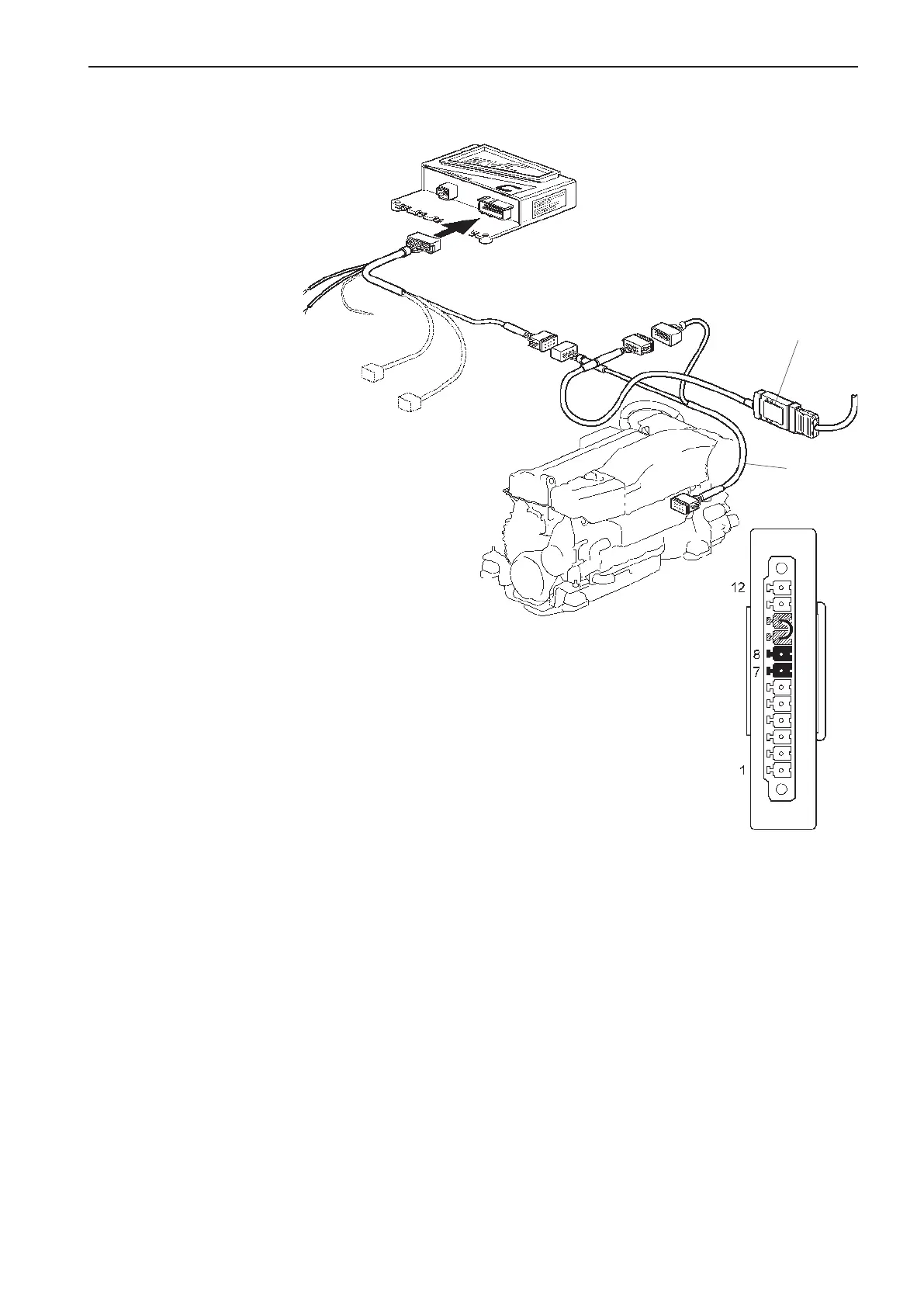
Installation order (Interface Out)
NOTE! The interface works at different speeds/baud
rates, depending on whether it is used as an in or out
interface.
Connect the Y connector (2) between the PCU and
the engine, as in the figure.
Change the interface baud rate by jumpering Pin 9
and Pin 10 on the screw terminal, as in the figure.
Connect the interface to the 12-pin connector on the
Y connector, as in the figure.
NOTE! Fix the interface in a suitable place, using a
tie wrap or screw.
Throttle diode (A):
Constant light -
Input signal is valid, i.e. between 4–20 mA.
Flashes (10 Hz) -
Input signal is < 4 mA or > 21 mA.
Switched off -
Other cases.
Slip diode (B):
Constant light -
Input signal for slip is valid, i.e. between 4-20 mA.
Flashes (10 Hz) -
Input signal is < 4 mA or > 21 mA.
Switched off -
Other cases.
NOTE! Also applies to the Out interface.
1
2
PCU
4-20 mA
Gear diode (C):
Constant light -
Input signal for Reverse or Forward is > 6 V.
Flashes (10 Hz) -
Input signal for Reverse and Forward is > 6 V (at the
same time).
Switched off -
Other cases.
Power diode (D):
Constant light -
The unit has power supply.
Flashes (1 Hz) -
No communication on the CAN bus.
Flashes (10 Hz) -
Communication on the CAN bus.
Switched off -
Other cases.
81
EVC-C Installation procedure, helm