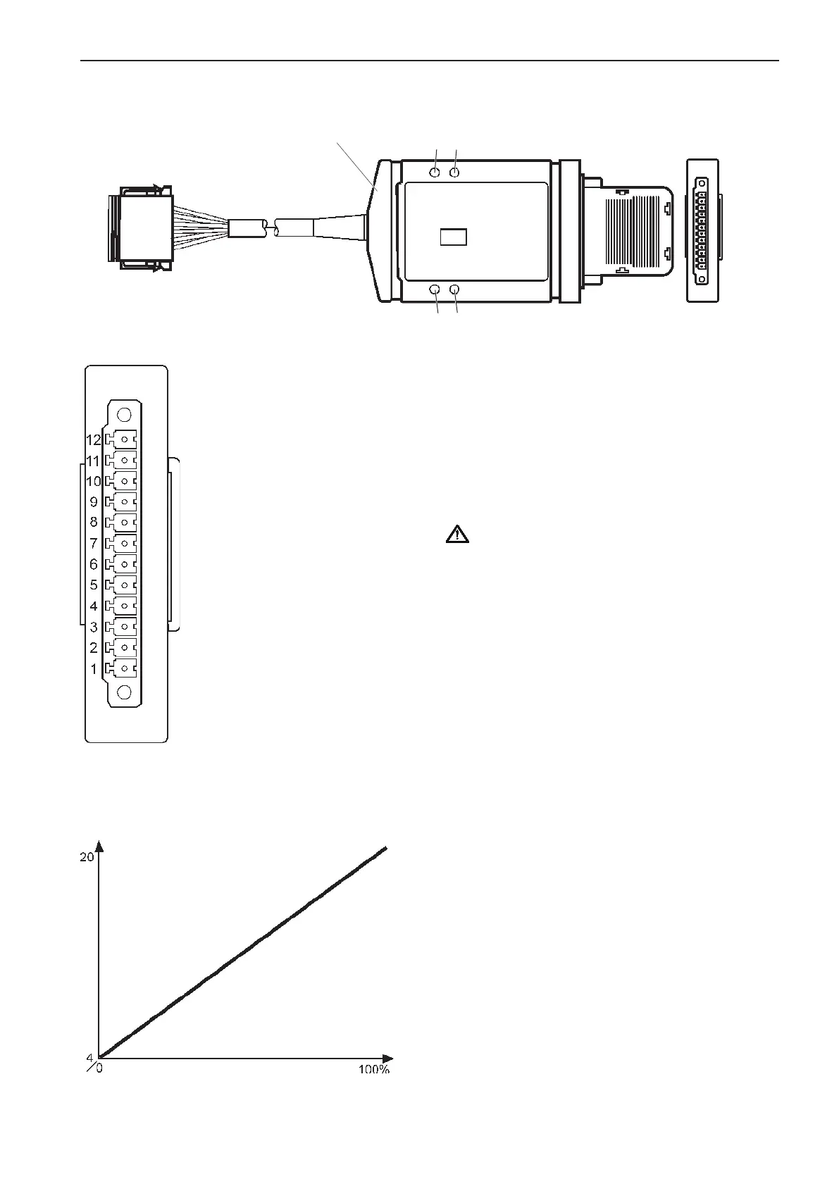
Interfaces for the EVC-C system, 4–20 mA
A
B
C D
Pin 1
1
Pin 12
mA
Throttle / Slip
Pin 12: - Negative
Pin 11: + 10-28 VDC
Pin 10: CLOSED : Output (7-8)
Pin 9: OPEN : Input (1-6)
Pin 8: - Slip out 200-600 ohm
Pin 7: + Slip out 4-20 mA
Pin 6: - Slip 200 ohm
Pin 5: + Slip 4-20 mA
Pin 4: REV 10-28 VDC = Engage
Pin 3: FWD 10-28 VDC = Engage
Pin 2: - Throttle 200 ohm
Pin 1: + Throttle 4-20 mA
Description
The interface makes it possible for Volvo Penta cus-
tomers to choose controls from other suppliers than
Volvo Penta, to control the accelerator, gear and slip
on Volvo Penta EVC-C engines.
IMPORTANT! Volvo Penta has developed and
tested the entire EVC system and its compo-
nents. However, components supplied from
manufacturers other than Volvo Penta, or incor-
rectly installed components can make the sys-
tem fail to work correctly. In these cases, Volvo
Penta does not accept any responsibility.
NOTE! The interface functions for both 12 V and 24
V installations.
79
EVC-C Installation procedure, helm