wc_tx001951gb.fm
45
E 3000 Operation
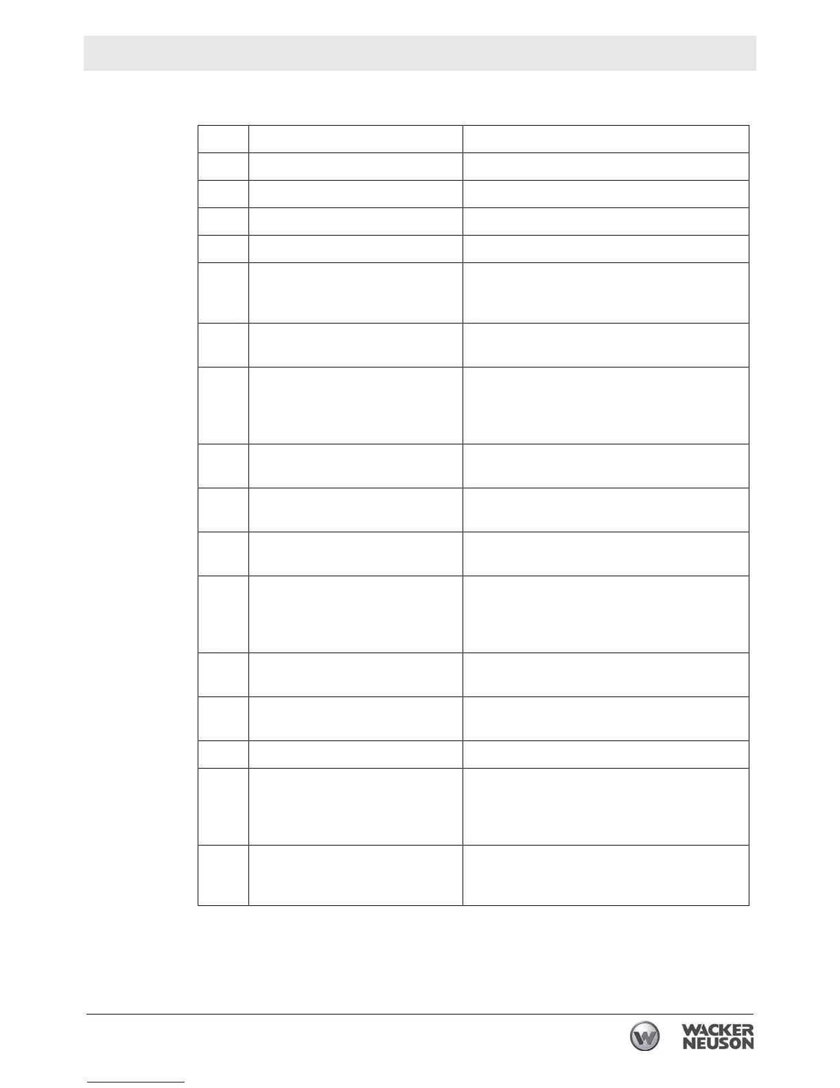
4.6 Control Panel Components
Ref Description Function
a Main breaker 1 Controls power to electrical circuit 1.
b Hour meter Meters usage of the machine.
c Main breaker 2 Controls power to the pump circuit (20A)
d Circuit 2 GFCI Provides protection for the operator.
e Temperature control
Allows the user to control the HTF target
application temperature.
Shows the actual temperature of the HTF.
f Cab light ON-OFF switch Switches electric power ON and OFF to the
cab light.
g Hose rewind ON-OFF (right and
left) switch
Controls power to the hose rewind motor.
This switch has two ON modes—one each in
the up and down positions. OFF mode is in
the middle position.
h Burner ON-OFF switch Switches electric power ON and OFF to the
burner.
i Pump 2 ON-OFF switch Switches electric power ON and OFF to
Pump 2.
j Pump 1 ON-OFF switch Switches electric power ON and OFF to
Pump 1.
k HTF fill switch This momentary switch bypasses the low-
level shut-down device and provides power
to the pumps. It is used when filling the HTF
reservoir after a low level fault.
l Low level fault indicator Illuminates to indicate a low HTF level condi-
tion.
m Burner fault indicator Illuminates to indicate a burner fault condi-
tion.
n Circuit 1 GFCI Provides protection for the operator.
o Thermal switch (snap switch)
Disconnects power to the burner circuit in the
event of an over-temperature condition. This
switch opens at 88°C (190°F). This switch
must be manually
reset.
p HTF low-level reset switch (mod-
ule is located inside the auxiliary
control panel)
Pressing this switch resets the low-level
shut-down device.