Installation and Initial Operation 40075165 Markoprint integra PP108
Page 47 of 104 GB
Connecting the optional Shaft Encoder
If more options will be used simultaneously, a splitter-box (Art.-No.: 72900545) can
used.
Requirements
The optional shaft encoder is mounted at the production line.
Ideally runs the measuring wheel of the shaft encoder on the conveyor belt, near
the print system.
Instruction
Please connect the optional shaft encoder with the print system as follows:
If necessary install the optional shaft encoder on the production line and
connect it to the option-connection socket.
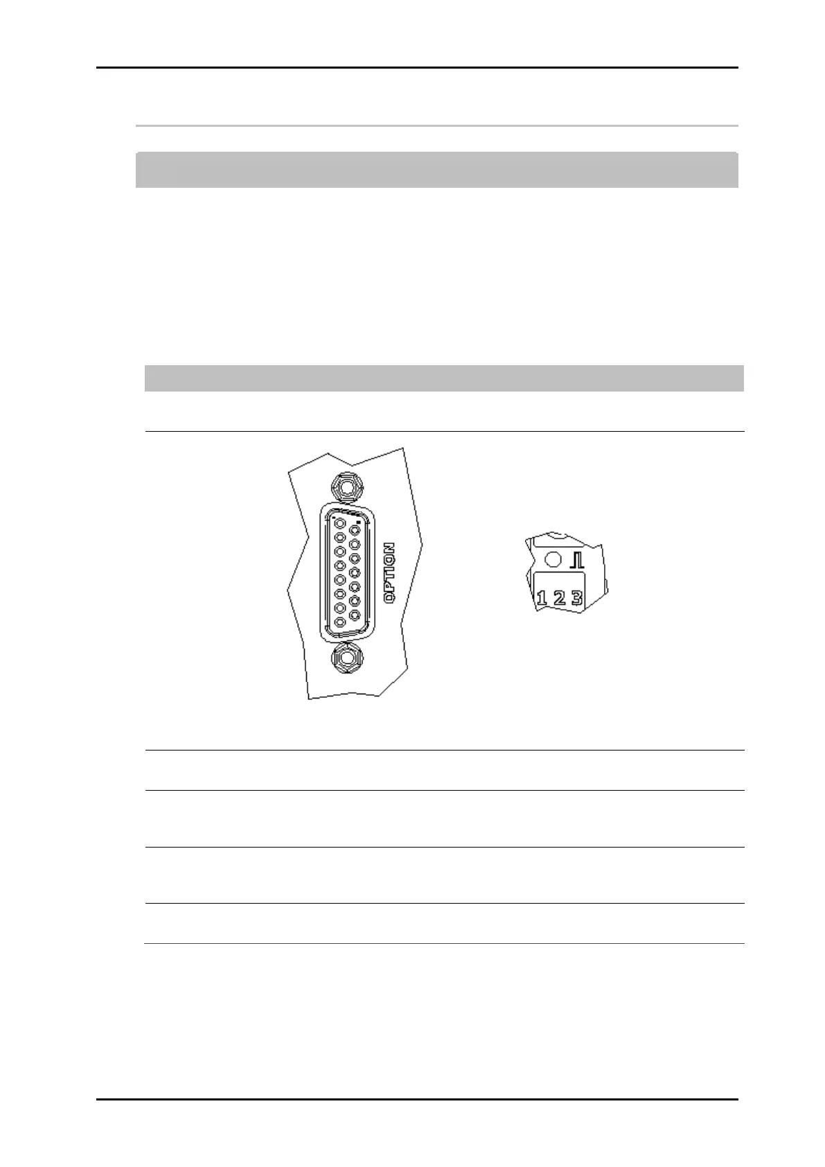
Fig. 10: Option-Socket (Sub-D 15-pole) on the system-back and Sensor-LED on the back side of
the system
Set the system-clock to Shaft encoder by the iDesign software. (System
settings – Print parameter)
Set the shaft encoder resolution by the iDesign software. 600 dpi with the
delivered shaft encoder with friction wheel from Weber (600 dpi optimized).
(System settings – Print Parameter)
Set the intensity by the iDesign software so, that the desired effective
resolution can be reached (180 dpi is standard). (System settings – Print
parameter)
The Sensor / Encoder LED lights red, if the shaft encoder isn’t connected or
doesn‘t rotate.