Tech. Dok. / L23 880 02 / 05.99.01 © MICHAEL WEINIG AG
Operating elements
2-7Profimat 23 E
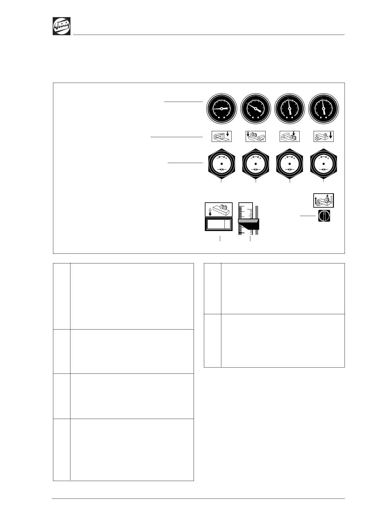
P 5 Cycled infeed roller (optional)
Left = Cycle infeed roller
downwards, surfacing
Right = Cycle infeed roller upwards,
straightening
Feed rollers, height indication
B 1a Bottom edge of feed roller in front of top
spindle to table, height indication on timber
infeed
B 1b (optional) instead of B 1a
2
4
6
8
10
12
14
16 2
4
6
8
10
12
14
16
2
4
6
8
10
12
14
16
2
4
6
8
10
12
14
16
Pneumatic control panel
P 1 Pressure circuit 1, transport roller
before 1st bottom spindle
(straightening) (optional) Hold-down
pressure of transport rollers before the
straightening spindle, raw timber
Basic setting:
Workpieces < 100 x 100 mm: appr. 1 – 4 bar
Workpieces > 100 x 100 mm: appr. 3 – 6 bar
P 2 Pressure circuit 2, steel feed rollers
Set hold-down pressure of the steel rollers
before the top spindle, raw timber
Basic setting: approx. 2 – 3 bar
P 3 Pressure circuit 3, rubber feed rollers
Hold-down pressure of the rubber rollers after
the top spindle, finished timber
Basic setting: approx. 2 – 3 bar
P 4 Pressure circuit 4, hold-down pressure of
chipbreaker before top spindle (optional)
Hold-down pressure of chipbreaker before top
spindle, raw timber
Basic setting: approx. 2 – 3 bar
P 1
P 5
P 4 P 3 P 2
0000 0
26
10
B 1aB 1b
Pressure gauge
Hold-down pressure
of feed rollers
Symbol
for pressure circuit
Pressure control
Pull knob out to adjust