Tech. Dok. / L23 880 02 / 01.00.02 © MICHAEL WEINIG AG
Basic setting
4-9Profimat 23 E
0020 0
0000 0
0020 0
0063 0
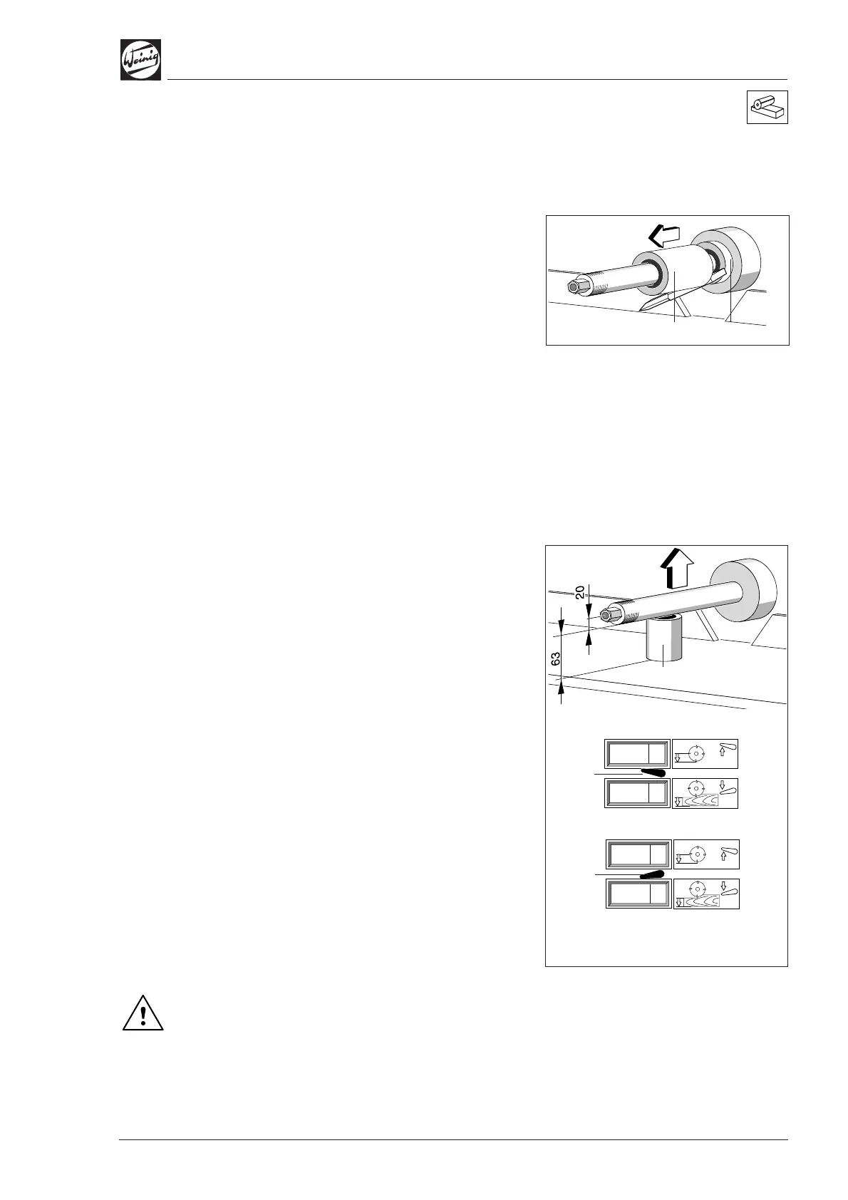
Top spindle
Axial basic setting
• Clamp setting straight edge between spacer
ring (1) 10.0 mm (0.394") and spindle ring (2)
63.0 mm (2.480").
• Release clamp and axially adjust spindle until
setting straight edge is aligned with fence.
• Set numerical indicator to 10.0 mm (0.394")
(see page 4-1).
Radial basic setting
• Raise pressure elements before and after top
spindle if necessary so that they do not rest on
the machine table when adjusting settings.
• Plane a test piece and measure timber height.
• Set numerical indicator to measured value
(see page 4-1).
Machines with two-fold indication (optional):
(A) Spindle radius:
• Lever (3) up.
• Set upper indicator to 20.0 mm (0.787") or half
of spindle diameter by means of the switch and
button.
(B) Spindle ring height:
• Lever (3) down.
• Place measured spindle ring (1) – 63.0 mm
(2.480") in this case – on machine table (2).
• Release spindle clamp and move spindle up
towards spindle ring until spindle ring can just
be moved under the spindle
• Set lower indicator to 63.0 mm (2.480") (see
page 4-1).
Note any chip removal on the last bottom spindle.
Set timber height, change tool radius
The timber height and tool radius can be set
directly, as with the left-hand spindle, when these
basic settings have been obtained.
The adjusting spindle must not be turned
when changing lever (3) from radius to width
or height indication! This applies for both
motor-driven and manual adjustment.
(2)
(1)
(2)
(1)
(A)
(B)
(3)
(3)