Tech. Dok. / L23 880 02 / 01.00.02 © MICHAEL WEINIG AG
Basic setting
4-7Profimat 23 E
0020 0
0000 0
0020 0
0063 0
Left-hand spindle
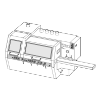
Axial basic setting
• Position spacer ring 10.0 mm (0.394") on
spindle.
• Position setting straight edge on spacer ring.
• Release clamp and adjust spindle in axial
direction until setting straight edge is aligned
with table.
• Set numerical indicator to 10.0 mm (0.394")
(see page 4-1).
Adjust for any chip removal on the last bottom
spindle (see page 4-12).
Radial basic setting
• Plane a test piece and measure timber width.
• Set numerical indicator to measured value (see
page 4-1).
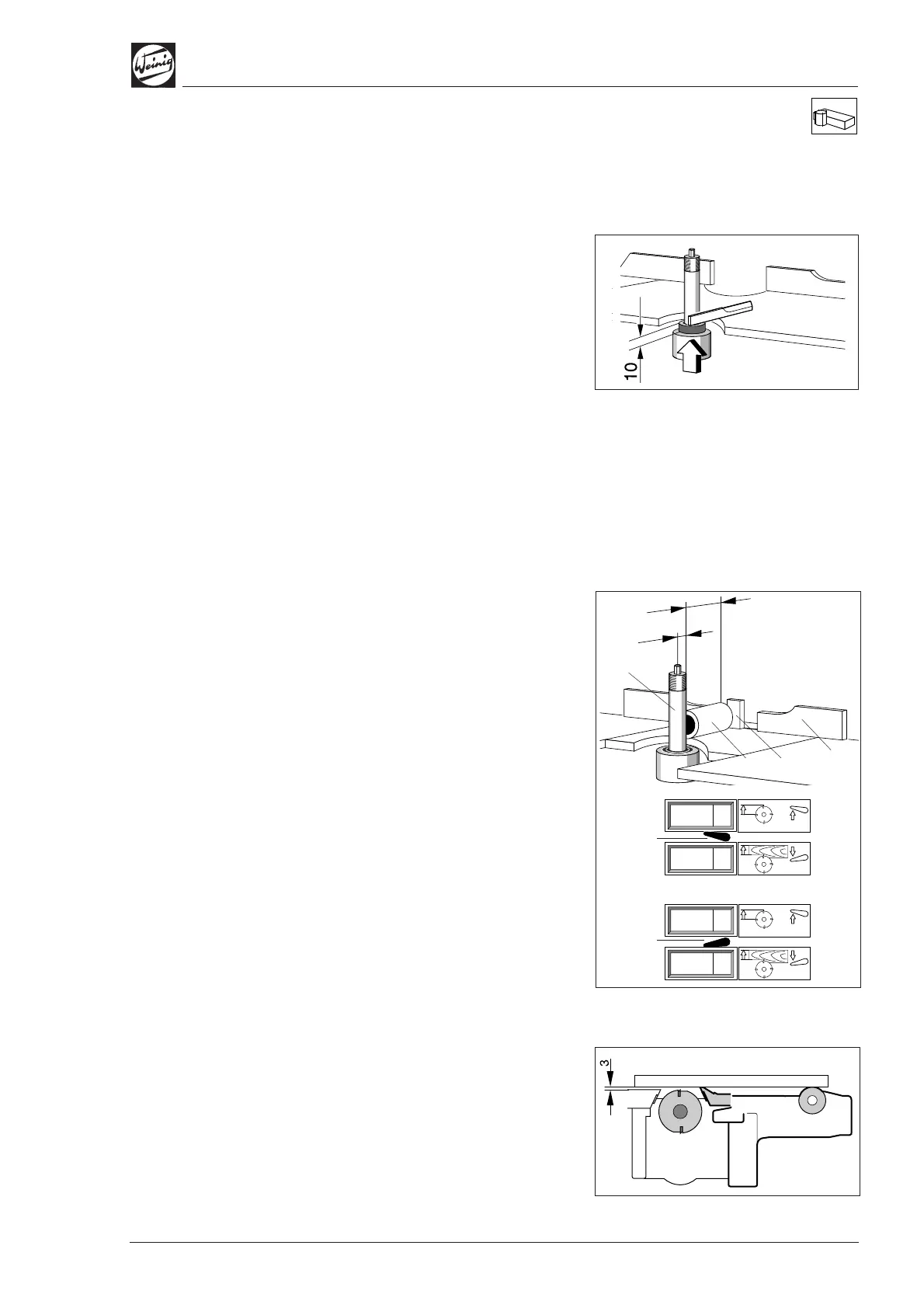
Machines with DigiSet counter (optional):
(A) Spindle radius
• Move lever (5) upwards.
• Set upper indicator to 20.0 mm (0.787") by
means of crank handle.
(B) Spindle ring length
• Move lever (5) downwards.
• Place measured spindle ring (1) – 63.0 mm
(2.480") in this case – against fence (2).
• Release spindle clamp and move spindle
towards fence until spindle ring can just be
moved.
• Set lower indicator to basic setting of 63.0 mm
(2.480") (see page 4-1).
Pressure elements before and after
tool
• Set pressure elements after tool in relation to
tool with the aid of the setting straight edge.
• Then set pressure elements before tool so that
they are 3 mm (0.125") in front of the tool.
When the basic settings have been made for the
spindle and pressure elements, the entire assem-
bly must be set to the required workpiece width.
(B)
(5)
(5)
(A)
Ø 40
63
20
(1)
(2)
(3)
(0.125")