Tech. Dok. / L23 880 02 / 05.99.01 © MICHAEL WEINIG AG
Machine options
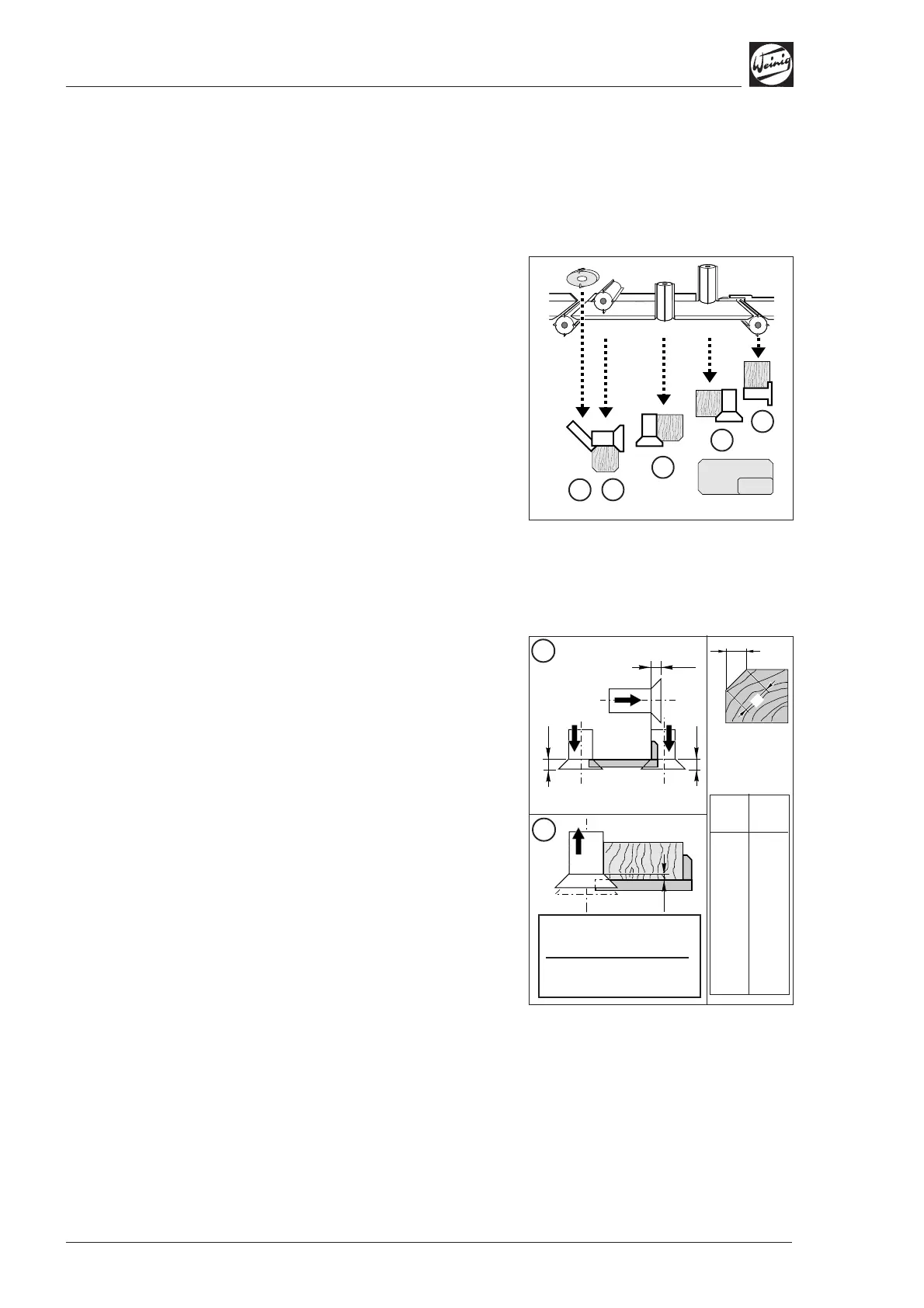
6-8 Profimat 23 E
b = Bevel
width
l = Bevel
length
l
[mm]
1.4
2.8
4.2
5.6
7.0
8.4
9.8
11.2
12.6
14.0
b
[mm]
1
2
3
4
5
6
7
8
9
10
Cutter height 14 mm
– Bevel width (b) 5 mm
= Set value for numerical
indicator 9 mm
14
14
14
b
l
5
5
4
3
2
1
A
B
Bevel unit
Sequence of work, bevel unit and
bevel cutter
A workpiece is to be bevelled on four sides:
Step 1: Rebate groove
Step 2: Bevel bottom right
Step 3: Bevel bottom left
Step 4: Bevel top right
Step 5: Bevel top left by bevel unit
• Fit bevel cutter behind cutterheads as shown in
diagram.
Axial spindle setting when using
bevel cutters and bevel unit
A = Bevel width 0 mm:
The bevel cutters (tool height 14 mm) must be
axially positioned behind the fence or under the
table for a bevel size of 0 mm; in other words:
• Axially adjust right-hand, left-hand and top
spindle to set value = 14 mm as shown on
numerical indicator.
B = Bevel width x mm:
The bevel width (b) is determined by the operator
through axial adjustment of the spindles. The set
value for the numerical indicator is calculated as
follows:
• Set value = 14 mm – bevel width