Tech. Dok. / L23 880 02 / 05.99.01 © MICHAEL WEINIG AG
Machine options
6-12 Profimat 23 E
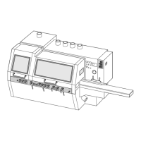
Groove guide
Function
Prevents short parts or parts with uneven ends
from running off the fence. Grooves are cut into
the workpiece by a groove cutter on the
straightening spindle. The timber is guided
through the machine by the grooves in the groove
bed. The outer right-hand groove (1) or the
second groove (2) acts as the main guide and
corresponds exactly with the width of the cut
groove. The other ridges are slightly narrower.
The guide grooves are planed off on the last
bottom spindle.
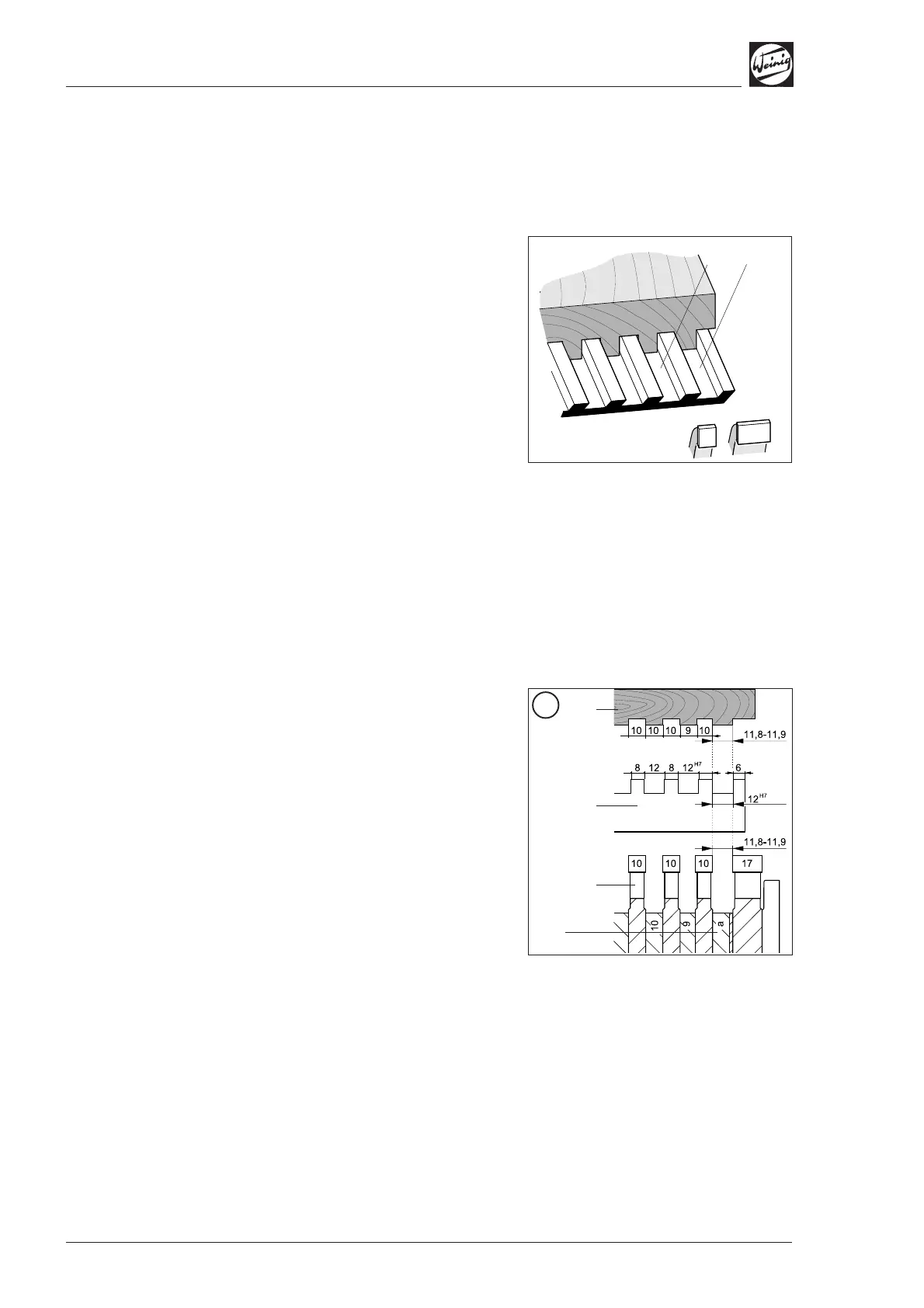
Radial basic setting of the edge-
jointing spindle
• Move the edge-jointing spindle approx. 0.2 mm
forwards in relation to the fence so that the
workpiece is guided in the groove and not along
the fence.
Axial specifications
The cutters must be assembled and mounted as
shown in Fig. A if the timber is guided in the first
groove.
(1) Timber
(2) Grooved table plate
(3) Groove cutters
Groove width (a) as a function of the
timber length
If the first ridge is cut off from the right on
account of the profile shape, the workpiece must
be guided by the second groove. The groove
cutters must be assembled as shown in Fig. B.
(1)
(2)
A
(1)
(2)
(3)
(a)