Tech. Dok. / L23 880 02 / 01.00.02 © MICHAEL WEINIG AG
Basic setting
4-12 Profimat 23 E
Bottom spindle
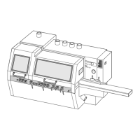
Set chip removal
The table plate must be adjusted upwards after
the last bottom spindle so that the underside of
the timber can be finish-planed.
• Unscrew table plate.
• Place 0.5 mm (0.20") shim supplied between
base and table plate.
Chip removal is impossible without the shim.
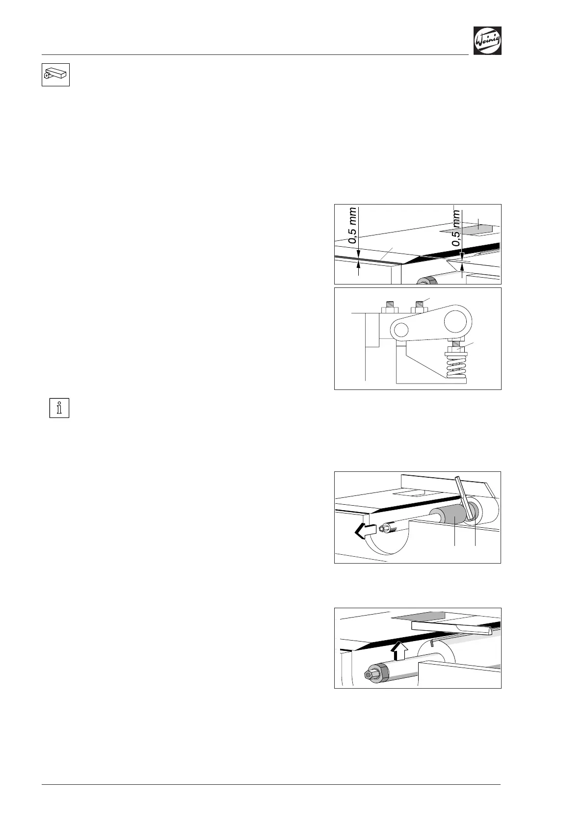
Table roller
• Adjust table roller (2) to match table height.
On the rear of the table:
• Adjust table roller up/down by means of
adjusting screw (3).
• Adjust spring pressure via spring pressure
element (4) if necessary (set to basic position
by manufacturer).
If the spindle is set for chip removal, all spindles
must be raised in relation to the outfeed table by
the amount of chip removed.
Axial basic setting
• Clamp setting straight edge between spacer
ring (1) 10.0 mm (0.394") and spindle ring (2)
63.0 mm (2.480").
• Release clamp and adjust spindle in axial
direction until setting straight edge is aligned
with fence.
• Set numerical indicator to 10.0 mm (0.394").
Radial basic setting
• Fit a dimensioned tool, radius 62.5 mm
(2.460") in this case.
• Place setting straight edge on outfeed table.
• Release clamp for spindle slide and adjust tool
in relation to setting straight edge.
• Set numerical indicator to 62.5 mm (2.460")
(see page 4-1).
(1)
(2)
(4)
(3)
(1)
(2)