Tech. Dok. / L23 880 02 / 05.99.01 © MICHAEL WEINIG AG
Troubleshooting
7-1Profimat 23 E
Designation
S 301 Q
S 101 Q
S 501 Q
S 502 Q
S 503 Q
S 504 Q
S 511 Q
S 512 Q
S 551 Q
S 552 Q
S 5017 Q
S 5018 Q
S 5020 Q
S 5021 Q
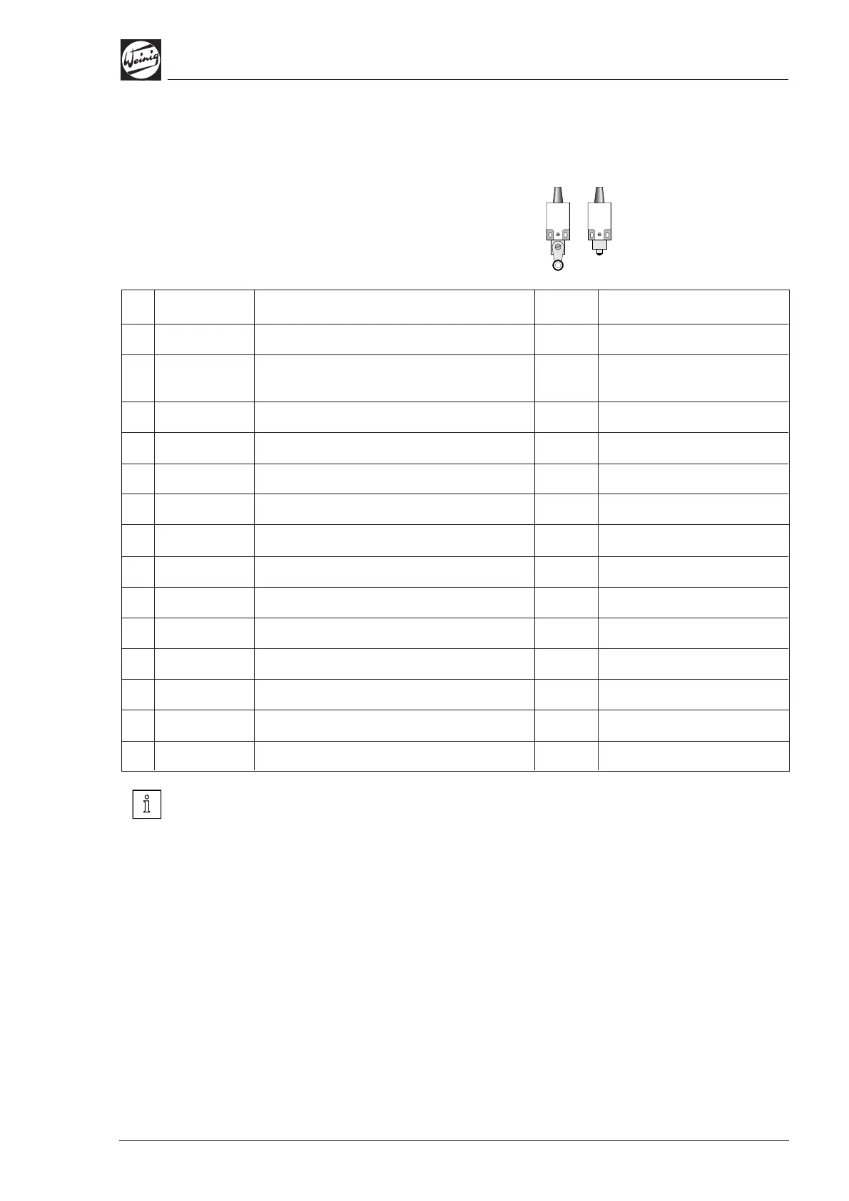
Summary of limit switches
Check that limit switches are functioning
correctly if machine functions are not executed.
Location
Feed flap
Beginning of hood above
straightening spindle
Feed beam near top spindle
Feed beam near top spindle
Behind pressure shoe
Behind pressure shoe
Left-hand spindlel
Left-hand spindle
Top spindle
Top spindle
Feed beam of universal spindle
No.
1
2
3
4
5
6
7
8
9
10
11
12
13
14
Optional
–
–
–
–
–
–
ATS
ATS
Optional
Optional
ATS
ATS
Optional
Optional
Function
Limit switch for infeed flap
Limit switch for hood
Limit position, feed beam, max.
Limit position, feed beam, min.
1st top spindle, max.
1st top spindle against feed beam
Left-hand spindle max.
Left-hand spindle min.
Feed rate max.
Feed rate min.
Top spindle max.
Top spindle min.
Pneumatic converter, 1st top spindle
Clamp, universal spindle
If an optional control system or supplementary
equipment are installed, additional limit switches
are installed on the controlled axes.