TRANSMISSION
L3301, L3901, L4701, WSM
3-S25
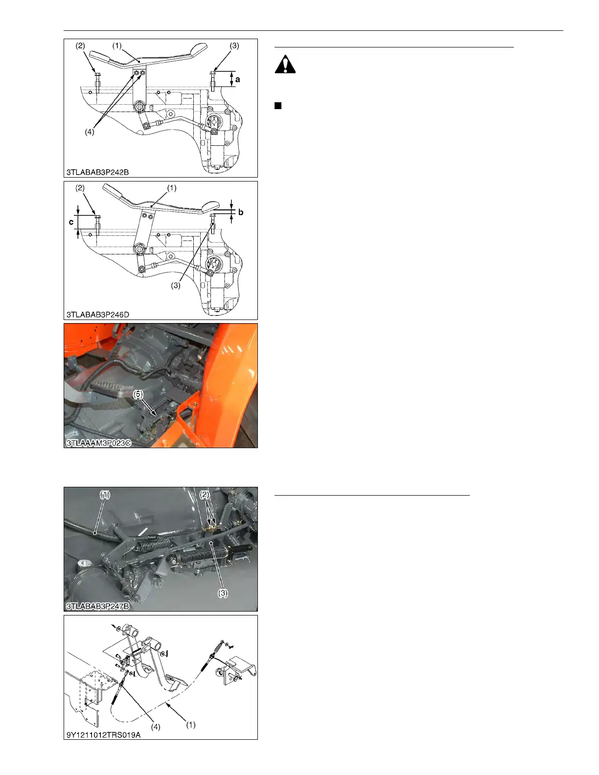
Cruise Control Linkage and Maximum Travel Speed
• Stop the engine when adjusting the cruise control linkage
and pedal stroke.
• Be sure to adjust the HST neutral position.
• Be sure to check whether the "traveling speed coefficient"
is suitable for tire size.
1. Loosen the HST pedal mounting screws (4) and tighten the
screws (4) while pulling up the front of HST pedal (1).
2. Adjust the height a of the pedal stopper bolt (Forward) (3) to
approx. 25 mm (0.98 in.) from the step.
3. Operate the tractor actually and make whether the tractor can
put on sufficient speed.
4. Set the cruise control lever to fully forward (Maximum position).
HST pedal also tilts.
5. Measure the clearance b between bottom of HST pedal and tip
of pedal stopper bolt (Forward) (3).
6. If the measurement is not within factory specification, adjust by
the cruise adjusting rod (5). (Cruise Linkage Adjustment.)
7. Shorten the pedal stopper bolt (Reverse) (2) to the position
where the length of the bolt is not touched to the HST pedal (1)
even if the HST pedal is fully depressed rearward.
8. Lengthen the length of the pedal stopper bolt (Reverse) (2)
gradually with the HST pedal fully depressed rearward to
contact to the HST pedal.
(Reference)
• Height "a": 25 mm (0.98 in.)
• Clearance "b": 2 to 6 mm (0.08 to 0.2 in.)
• Height "c": 15 mm (0.59 in.)
9Y1211012TRS0021US0
Adjusting Cruise Control Release Linkage
1. Adjust the brake pedals free travel first.
2. Depress one of the brake pedal to make sure the cruise control
is not released. Also depress both the brake pedals coupled
together to make sure that the cruise control is released.
3. If the cruise control does not work as above adjust with release
wire (1) as follows.
• Check to see that the threaded portion of the wire (1) rear
side is set at the end position. If not, set by lock nuts (2).
• Adjust by lock nuts (4) for the center of the threaded portion
of the release wire front side to come to the hook position.
• Make sure whether to move as above-mentioned 2.
• If not, adjust by lock nuts (4).
9Y1211012TRS0022US0
(1) HST Pedal
(2) Pedal Stopper Bolt (Reverse)
(3) Pedal Stopper Bolt (Forward)
(4) HST Pedal Mounting Screw
(5) Cruise Adjusting Rod
a: Stopper Bolt Height (Forward)
b: Clearance between HST pedal
and stepper bolt (Forward)
c: Stopper Bolt Height (Reverse)
F: Forward
R: Reverse
(1) Release Wire
(2) Lock Nut (Rear)
(3) Damper Stay
(4) Lock Nut (Front)