TRANSMISSION
L3301, L3901, L4701, WSM
3-S116
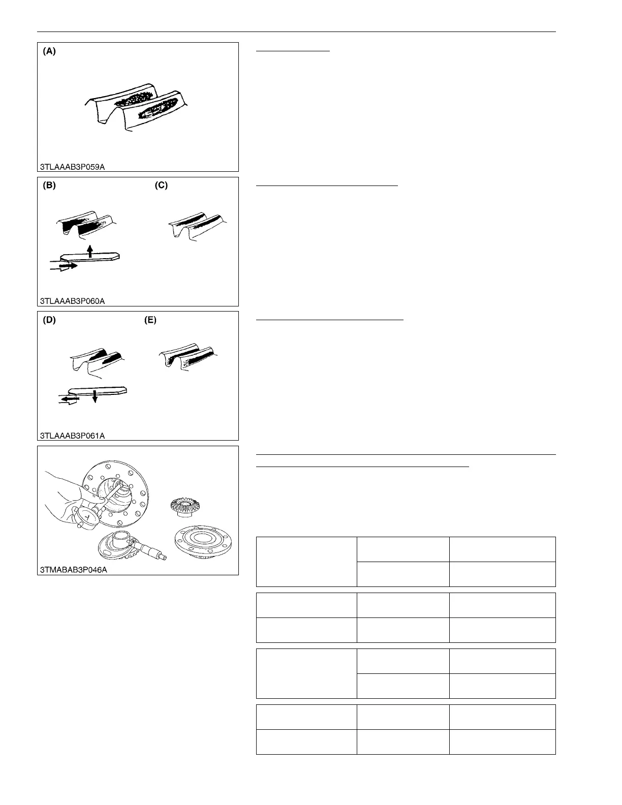
Proper Contact
More than 35 % red lead contact area on the gear tooth surface.
The center of tooth contact at 1/3 of the entire width from the
small end.
9Y1211012TRS0152US0
Heel Contact and Tip Contact
Replace the adjusting shim with thicker one to move the bevel
pinion shaft forward.
And place the left side shim to the right to move the bevel gear
rightward.
Repeat above until the proper tooth contact and backlash are
achieved.
9Y1211012TRS0153US0
Toe Contact and Base Contact
Replace adjusting shim with thicker one to move the bevel
pinion shaft forward.
And place the right side shim to the left to move the bevel gear
leftward.
Repeat above until the proper tooth contact and backlash are
achieved.
9Y1211012TRS0154US0
Clearance between Differential Case Bore (Differential Case
Cover Bore) and Differential Side Gear Boss
1. Measure the bore I.D. of the differential case and differential
case cover.
2. Measure the differential side gear boss O.D. and calculate the
clearance.
3. If the clearance exceeds the allowable limit, replace them.
9Y1211012TRS0155US0
(A) Proper Contact
(B) Heel Contact (C) Tip Contact
(D) Toe Contact (E) Base Contact
Clearance between
differential case bore and
differential side gear
boss
Factory specification
0.0500 to 0.151 mm
0.00197 to 0.00594 in.
Allowable limit
0.35 mm
0.014 in.
Differential case bore
I.D.
Factory specification
40.500 to 40.562 mm
1.5945 to 1.5969 in.
Differential side gear
boss O.D.
Factory specification
40.411 to 40.450 mm
1.5910 to 1.5925 in.
Clearance between
differential case cover
bore and differential side
gear boss
Factory specification
0.090 to 0.169 mm
0.00355 to 0.00665 in.
Allowable limit
0.35 mm
0.014 in.
Differential case cover
bore I.D.
Factory specification
40.540 to 40.580 mm
1.5961 to 1.5976 in.
Differential side gear
boss O.D.
Factory specification
40.411 to 40.450 mm
1.5910 to 1.5925 in.
 Loading...