FRONT AXLE
L3301, L3901, L4701, WSM
6-S13
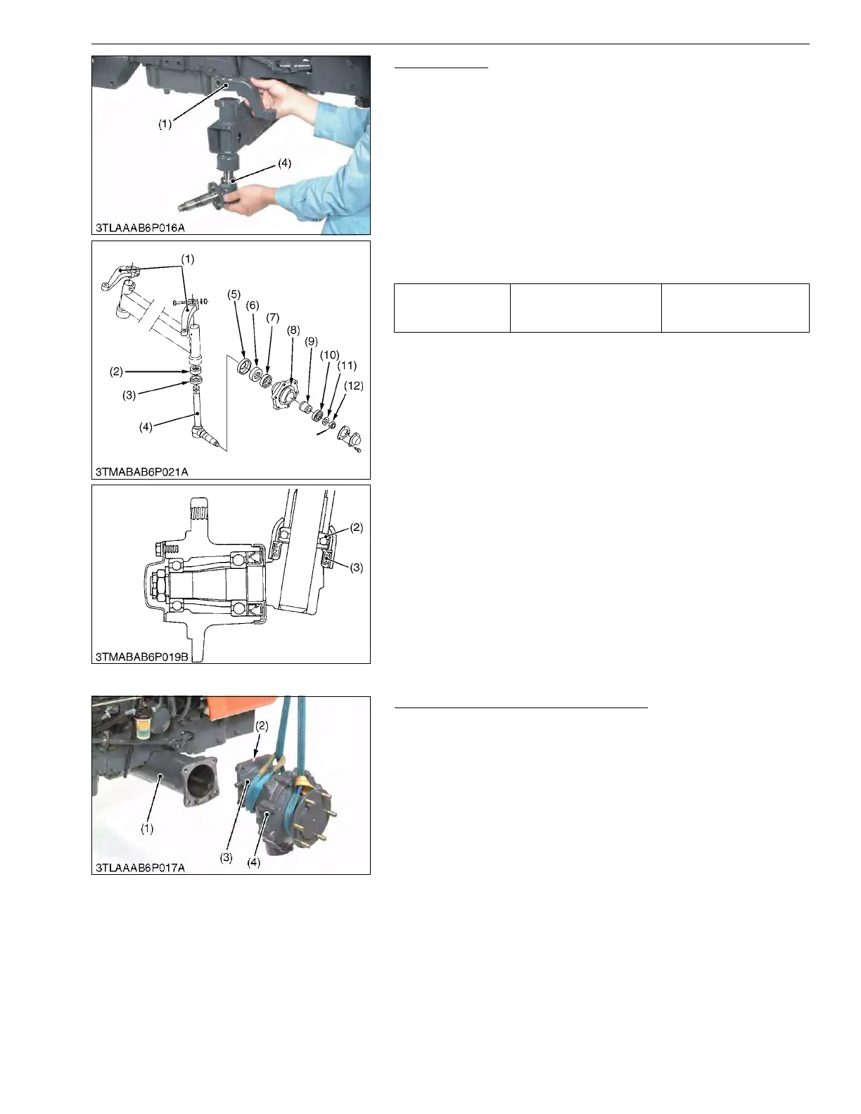
Knuckle Shaft
1. Remove the knuckle arm (1) and draw out the knuckle shaft (4)
from the front axle.
(When reassembling)
• Insert the thrust ball bearing (2) and oil seal (3), noting its
direction.
• Apply grease to the oil seals (3), (6).
• Do not interchange right and left knuckle arms.
• When lift the knuckle shaft, the knuckle arms must be mounted
so that the clearance between the knuckle arms and front axle
is 0.30 to 1.0 mm (0.012 to 0.039 in.).
• After reassembling, be sure to lubricate grease from grease
fitting.
9Y1211012FAS0014US0
[B] 4WD Model
Bevel Gear Case and Front Gear Case
1. Remove the bevel gear case mounting screws.
2. Remove the bevel gear case (3) and front gear case (4) as a unit
from the front axle case (1).
(When reassembling)
• Apply grease to the O-ring (2) and be careful not to damage it.
• Do not interchange right and left bevel gear case assemblies
and front gear case assemblies.
9Y1211012FAS0015US0
Tightening torque
Knuckle arm mounting bolt
and nut
78 to 90 N·m
7.9 to 9.2 kgf·m
58 to 66 lbf·ft
(1) Knuckle Arm
(2) Thrust Ball Bearing
(3) Oil Seal
(4) Knuckle Shaft
(5) Dust Cover
(6) Oil Seal
(7) Ball Bearing
(8) Front Wheel Hub
(9) Spacer
(10) Ball Bearing
(11) Washer
(12) Slotted Nut
(1) Front Axle Case
(2) O-ring
(3) Bevel Gear Case
(4) Front Gear Case
 Loading...