FRONT AXLE
L3301, L3901, L4701, WSM
6-S14
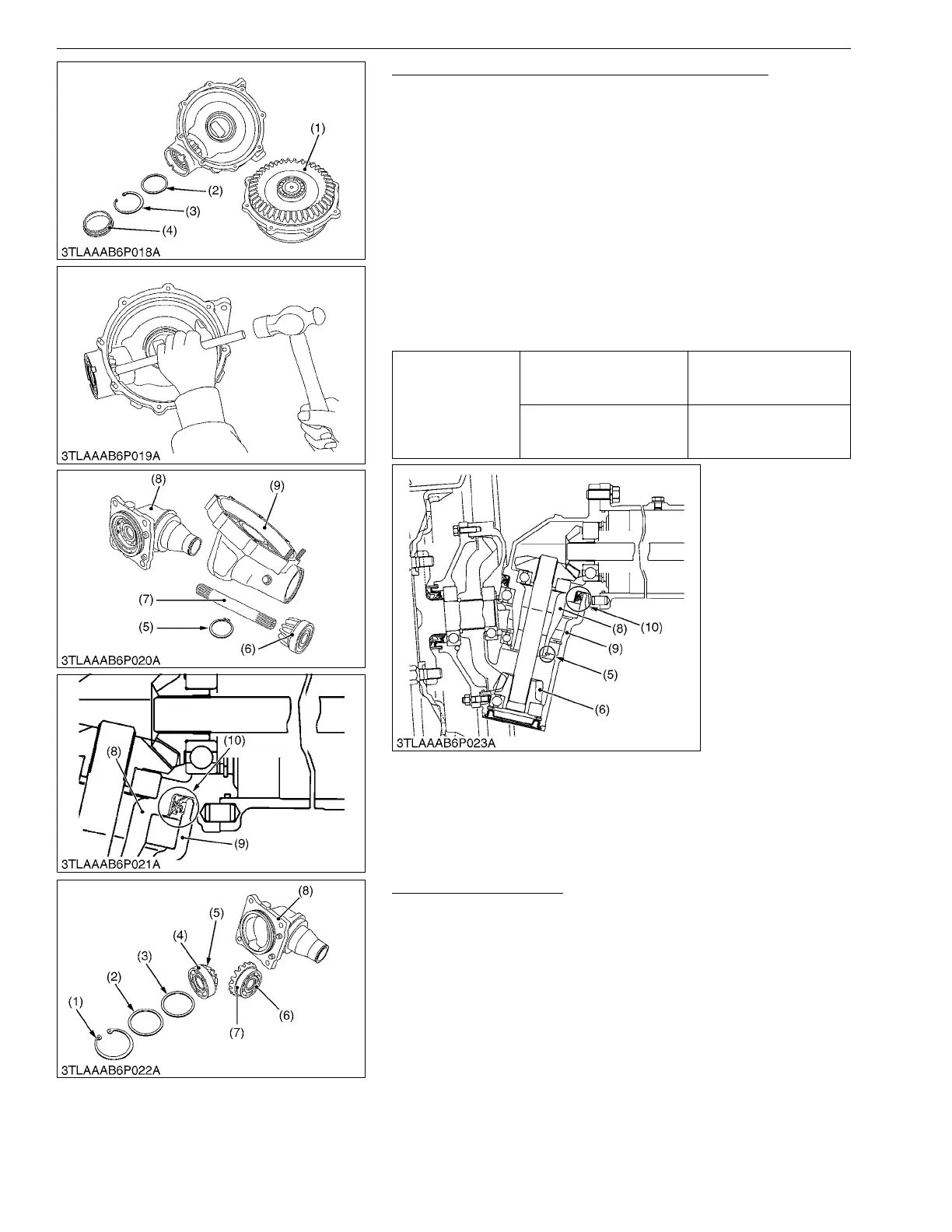
Bevel Gear Case, Axle Flange and Front Gear Case
1. Remove the plug (4).
2. Remove the internal snap ring (3) and shim (2).
3. Remove the axle flange (1).
4. Tap out the bevel gear (6) and ball bearing.
5. Draw out the bevel gear shaft (7).
6. Remove the external snap ring (5).
7. Tap the bevel gear case (8), and separate it from the front gear
case (9).
(When reassembling)
• Apply grease to the O-rings of axle flange (1).
• Tighten the axle flange mounting screws and nuts diagonally in
several steps.
• Install the oil seal (10) of bevel gear case, noting its direction as
shown in the figure below.
9Y1211012FAS0016US0
Bevel Gear Case Gears
1. Remove the internal snap ring (1).
2. Remove the bevel gears (5), (7) with ball bearings (4), (6), collar
(2) and shims (3).
(When reassembling)
• Install the same shims (3) have same thickness as before
disassembling.
9Y1211012FAS0017US0
Tightening torque
Axle flange mounting stud
bolt
12 to 15 N·m
1.2 to 1.6 kgf·m
8.7 to 11 lbf·ft
Axle flange mounting bolts
and nuts
24 to 27 N·m
2.4 to 2.8 kgf·m
18 to 20 lbf·ft
(1) Axle Flange
(2) Shim
(3) Internal Snap Ring
(4) Plug
(5) External Snap Ring
(6) Bevel Gear
(7) Bevel Gear Shaft
(8) Bevel Gear Case
(9) Front Gear Case
(10) Oil Seal
(1) Internal Snap Ring
(2) Collar
(3) Shim
(4) Ball Bearing
(5) Bevel Gear
(6) Ball Bearing
(7) Bevel Gear
(8) Bevel Gear Case
 Loading...