MicroBlaze Processor Reference Guide 145
UG984 (v2018.2) June 21, 2018 www.xilinx.com
Chapter 3: MicroBlaze Signal Interface Description
In general, MicroBlaze signals are synchronous to the Clk input signal. However, there are
some exceptions controlled by parameters as described in the following table.
Sleep and Pause Functionality
There are two distinct ways of halting MicroBlaze execution in a controlled manner:
• Software controlled by executing an MBAR instruction to enter sleep mode.
• Hardware controlled by setting the input signal Pause to pause the pipeline.
Software Controlled
When an MBAR instruction is executed to enter sleep mode and MicroBlaze has completed
all external accesses, the pipeline is halted and either the
Sleep, Hibernate, or Suspend
output signal is set.
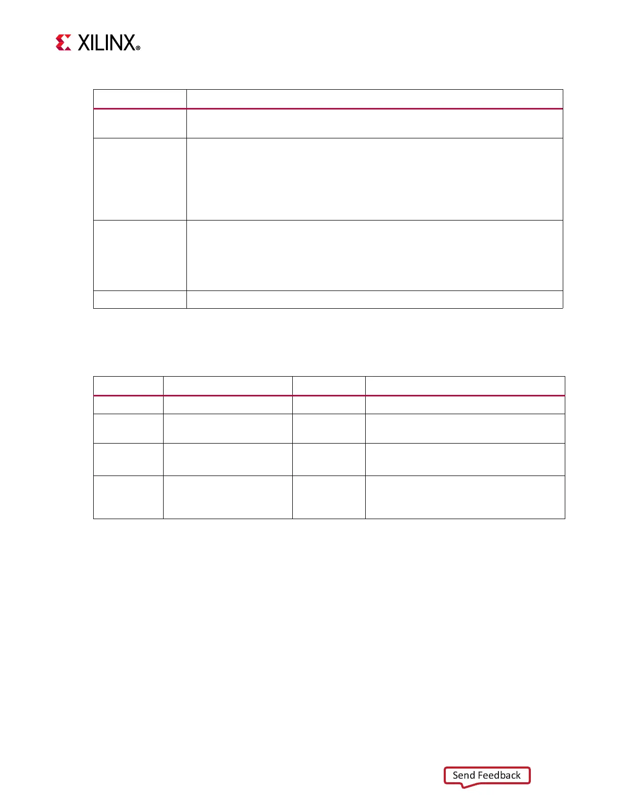
Table 3-2: Effect of Reset Mode inputs
Reset_Mode[0:1] Description
00
MicroBlaze starts executing at the reset vector, defined by C_BASE_VECTORS. This
is the nominal default behavior.
01
MicroBlaze immediately enters sleep mode without performing any bus access,
just as if a SLEEP instruction had been executed. The Sleep output is set to 1.
When any of the Wakeup[0:1] signals is set, MicroBlaze starts executing at the
reset vector, defined by C_BASE_VECTORS.
This functionality can be useful in a multiprocessor configuration, allowing
secondary processors to be configured without LMB memory.
10
If C_DEBUG_ENABLED is 0, the behavior is the same as if Reset_Mode[0:1] = 00.
If C_DEBUG_ENABLED is greater than 0, MicroBlaze immediately enters debug halt
without performing any bus access, and the MB_Halted output is set to 1. When
execution is continued via the debug interface, MicroBlaze starts executing at the
reset vector, defined by C_BASE_VECTORS.
11
Reserved
Table 3-3: Parameter Controlled Asynchronous Signals
Signal Parameter Default Description
Interrupt
C_ASYNC_INTERRUPT
Tool controlled
Parameter set from connected signal
Reset
C_NUM_SYNC_FF_CLK
2
Parameter can be manually set to 0 for
synchronous reset
Wakeup[0:1]
C_ASYNC_WAKEUP
C_NUM_SYNC_FF_CLK
Tool controlled
2
Set from connected signals
Can be manually set to 0 to override tool
Dbg_Wakeup
C_DEBUG_INTERFACE
0 (serial)
0: Clocked by Dbg_Update
1: Clocked by DEBUG_ACLK, synchronous
to
Clk