MicroBlaze Processor Reference Guide 72
UG984 (v2018.2) June 21, 2018 www.xilinx.com
Chapter 2: MicroBlaze Architecture
Reset, Interrupts, Exceptions, and Break
MicroBlaze supports reset, interrupt, user exception, break, and hardware exceptions. The
following section describes the execution flow associated with each of these events.
The relative priority starting with the highest is:
1. Reset
2. Hardware Exception
3. Non-maskable Break
4. Break
5. Interrupt
6. User Vector (Exception)
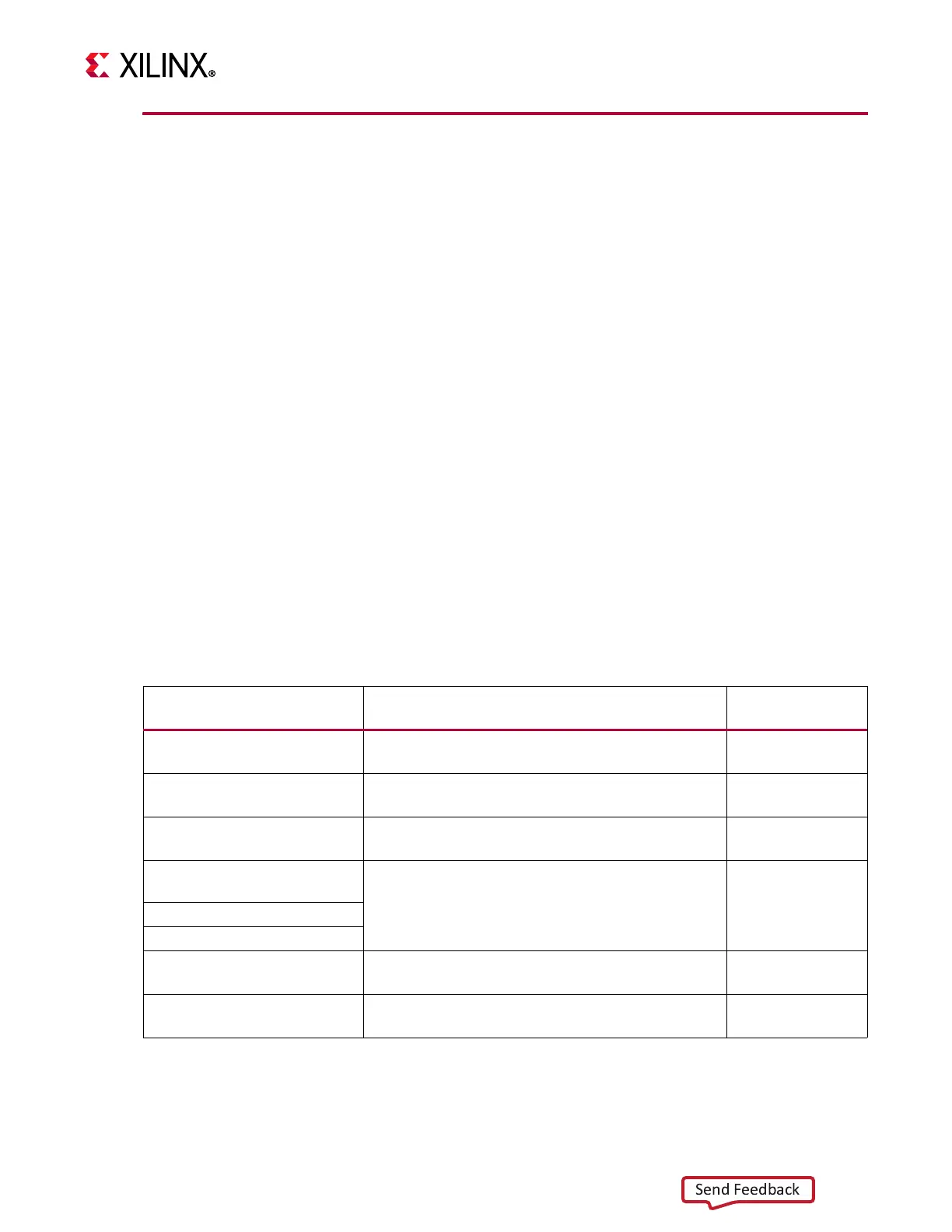
Table 2-39 defines the memory address locations of the associated vectors and the
hardware enforced register file locations for return addresses. Each vector allocates two
addresses to allow full address range branching (requires an
IMM followed by a BRAI
instruction). Normally the vectors start at address 0x00000000, but the parameter
C_BASE_VECTORS can be used to locate them anywhere in memory.
The address range 0x28 to 0x4F is reserved for future software support by Xilinx. Allocating
these addresses for user applications is likely to conflict with future releases of SDK support
software.
All of these events will clear the reservation bit, used together with the LWX and SWX
instructions to implement mutual exclusion, such as semaphores and spinlocks.
Table 2-39: Vectors and Return Address Register File Location
Event Vector Address
Register File
Return Address
Reset
C_BASE_VECTORS + 0x00000000 -
C_BASE_VECTORS + 0x00000004
-
User Vector (Exception)
C_BASE_VECTORS + 0x00000008 -
C_BASE_VECTORS + 0x0000000C
Rx
Interrupt
1
C_BASE_VECTORS + 0x00000010 -
C_BASE_VECTORS + 0x00000014
R14
Break: Non-maskable
hardware
C_BASE_VECTORS + 0x00000018 -
C_BASE_VECTORS + 0x0000001C
R16
Break: Hardware
Break: Software
Hardware Exception
C_BASE_VECTORS + 0x00000020 -
C_BASE_VECTORS + 0x00000024
R17 or BTR
Reserved by Xilinx for future
use
C_BASE_VECTORS + 0x00000028 -
C_BASE_VECTORS + 0x0000004F
-
1. With low-latency interrupt mode, the vector address is supplied by the Interrupt Controller.