MicroBlaze Processor Reference Guide 171
UG984 (v2018.2) June 21, 2018 www.xilinx.com
Chapter 3: MicroBlaze Signal Interface Description
Trace Interface Description
The MicroBlaze processor core exports a number of internal signals for trace purposes. This
signal interface is not standardized and new revisions of the processor might not be
backward compatible for signal selection or functionality. It is recommended that you not
design custom logic for these signals, but rather to use them using Xilinx provided analysis
IP. The trace signals are grouped in the TRACE bus. The current set of trace signals were last
updated for MicroBlaze v7.30 and are listed in
Table 3-16.
The mapping of the MSR bits is shown in Table 3-17. For a complete description of the
Machine Status Register, see “Special Purpose Registers” in Chapter 2.
The Trace exception types are listed in Table 3-18. All unused Trace exception types are
reserved.
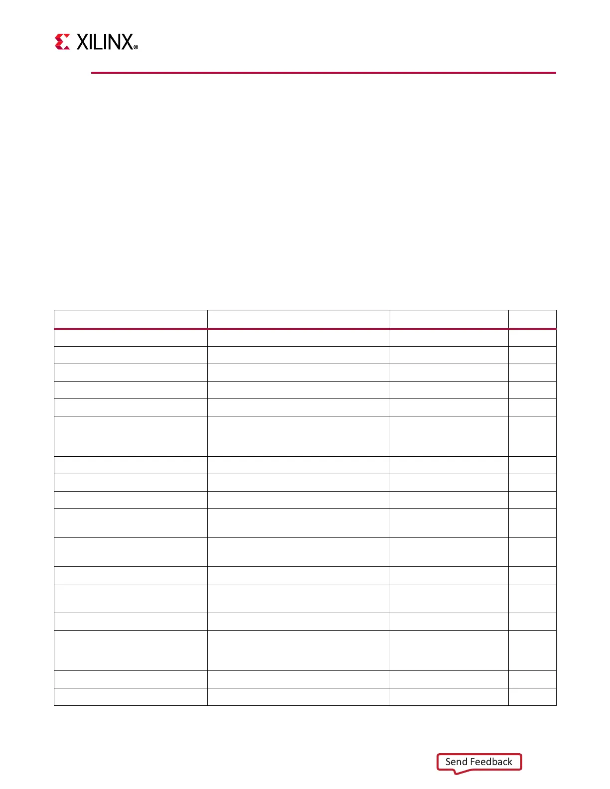
Table 3-16: MicroBlaze Trace Signals
Signal Name Description VHDL Type Direction
Trace_Valid_Instr Valid instruction on trace port.
std_logic
output
Trace_Instruction
1
Instruction code
std_logic_vector (0 to 31)
output
Trace_PC
1
Program counter
std_logic_vector (0 to 31)
output
Trace_Reg_Write
1
Instruction writes to the register file
std_logic
output
Trace_Reg_Addr
1
Destination register address
std_logic_vector (0 to 4)
output
Trace_MSR_Reg
1
Machine status register. The mapping
of the register bits is documented
below.
std_logic_vector (0 to 14)
1
output
Trace_PID_Reg
1
Process identifier register
std_logic_vector (0 to 7)
output
Trace_New_Reg_Value
1
Destination register update value
std_logic_vector (0 to 31)
output
Trace_Exception_Taken
1,2
Instruction result in taken exception
std_logic
output
Trace_Exception_Kind
1
Exception type. The description for the
exception type is documented below.
std_logic_vector (0 to 4)
2
output
Trace_Jump_Taken
1
Branch instruction evaluated true, that
is taken
std_logic
output
Trace_Jump_Hit
1,3
Branch Target Cache hit
std_logic
output
Trace_Delay_Slot
1
Instruction is in delay slot of a taken
branch
std_logic
output
Trace_Data_Access
1
Valid D-side memory access
std_logic
output
Trace_Data_Address
1
Address for D-side memory access,
where N = 32 - 64, determined by
parameter C_ADDR_SIZE
std_logic_vector (0 to N-1)
output
Trace_Data_Write_Value
1
Value for D-side memory write access
std_logic_vector (0 to 31)
output
Trace_Data_Byte_Enable
1
Byte enables for D-side memory access
std_logic_vector (0 to 3)
output