MicroBlaze Processor Reference Guide 148
UG984 (v2018.2) June 21, 2018 www.xilinx.com
Chapter 3: MicroBlaze Signal Interface Description
Hardware Controlled
When the Pause input signal is set to one and MicroBlaze has completed all external
accesses, the pipeline is halted and the
Pause_Ack output signal is set. This indicates to
external hardware that it is safe to perform actions such as stopping the clock, resetting the
processor or other IP cores. To continue from pause, the input signal
Pause must be cleared
to zero. In this case MicroBlaze continues instruction execution where it was previously
paused.
The Dbg_Continue output signal from MicroBlaze indicates that the debugger requests the
processor to continue from pause. External hardware should handle this signal and clear
pause after performing any other necessary hardware actions such as starting the clock.
After external hardware has set or cleared Pause, it is recommended to wait until
Pause_Ack is set or cleared before Pause is changed again, to avoid any issues due to
incorrectly detected pause acknowledge.
All signals used for hardware control (Pause, Pause_Ack, and Dbg_Continue) are
synchronous to the MicroBlaze clock.
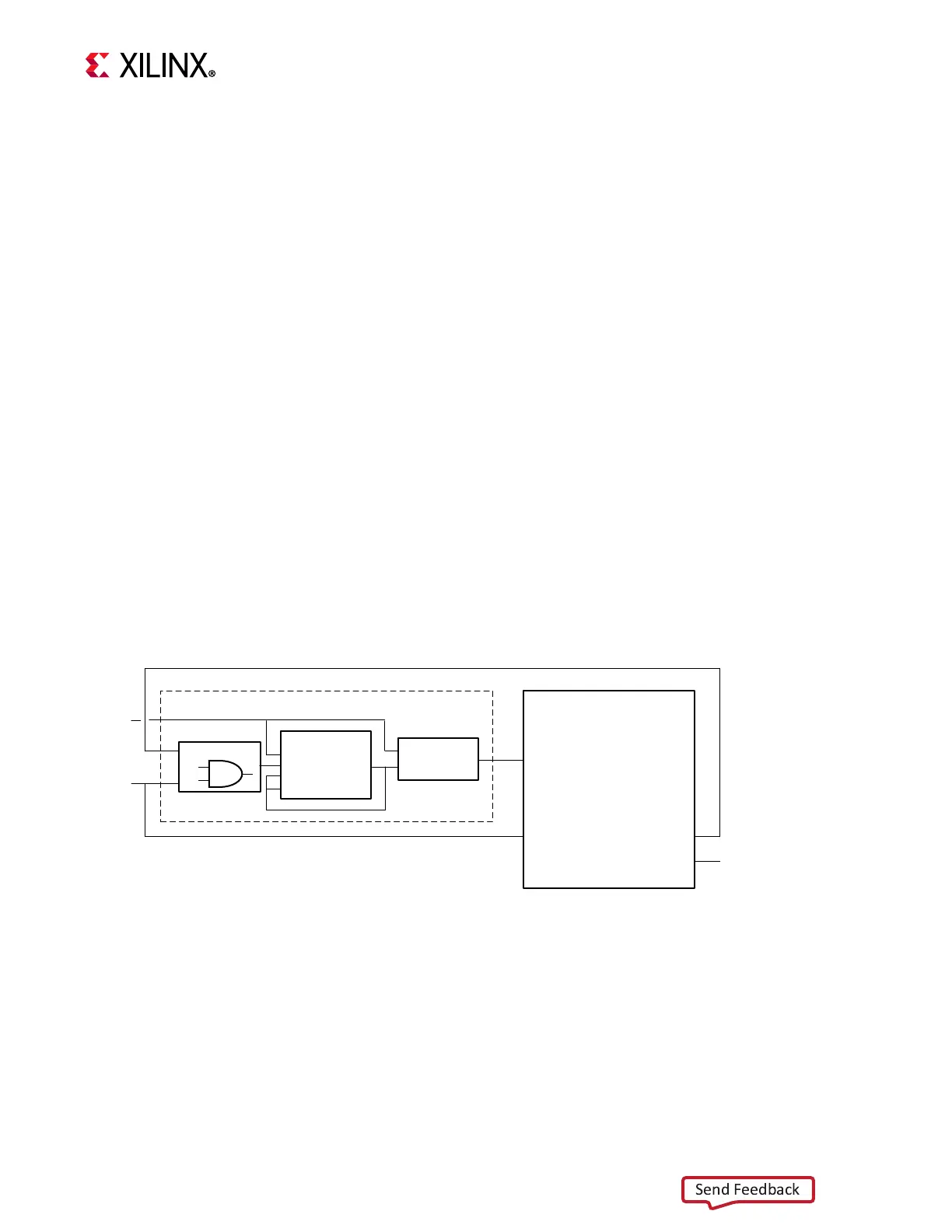
The block diagram in Figure 3-3 illustrates how to use the pause functionality to halt the
processor and how to implement clock control. In this example, Pause is an external
hardware signal that pauses processor execution and stops the clock. When
Pause is
cleared to zero, the clock is enabled and execution resumes. This example assumes that the
external logic monitors
Dbg_Continue, and clears Pause to allow debugging.
X-Ref Target - Figure 3-3
Figure 3-3: Pause Clock Control Block Diagram
MicroBlaze
C_ENABLE_DISCRETE_PORTS = 1
Utility Vector Logic
Binary Counter
CLK
SCLR
LOAD
L[0:0]
Q[0:0]
Clock Control
Utility Buffer
BUFGCE
Pause_Ack
Clk
Pause
Dbg_Continue
Pause
Clock
Dbg_Continue
;