ZCU106 Board User Guide 39
UG1244 (v1.0) March 28, 2018 www.xilinx.com
Chapter 3: Board Component Descriptions
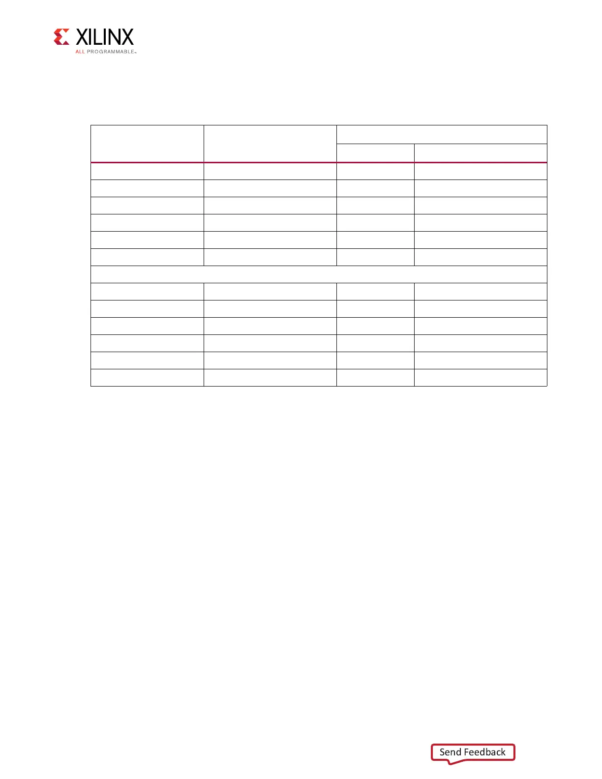
The connections between the SPI flash memory and the XCZU7EV MPSoC are listed in
Table 3-6.
The configuration and Quad SPI flash memory section of the Zynq UltraScale+ MPSoC
Technical Reference Manual (UG1085) [Ref 2] provides details on using the memory. For
more Quad SPI details, see the Micron MT25QU512ABB8ESF-0SIT data sheet at the Micron
website [Ref 15].
USB0 (MIO 52-63)
The USB interface on the PS-side serves multiple roles as a host or device controller. The
USB 3.0 interface is supported by the MPSoC GTR interface while the USB 2.0 capabilities of
the SMSC USB3320C controller are shared on a common USB 3.0 USB type A connector
(J96).
Table 3-6: Quad SPI Flash Memory Component Connections to MPSoC U1
XCZU7EV (U1) Pin Net Name
Quad-SPI U119 (LWR), U120 (UPR)
Pin # Pin Name
A25 MIO4_QSPI_LWR_DQ0 15 DQ0
C24 MIO1_QSPI_LWR_DQ1 8 DQ1
B24 MIO2_QSPI_LWR_DQ2 9 DQ2_WP_B
E25 MIO3_QSPI_LWR_DQ3 1 DQ3_RST_HOLD_B
A24 MIO0_QSPI_LWR_CLK 16 C
D25 MIO5_QSPI_LWR_CS_B 7 S_B
D26 MIO8_QSPI_UPR_DQ0 15 DQ0
C26 MIO9_QSPI_UPR_DQ1 8 DQ1
F26 MIO10_QSPI_UPR_DQ2 9 DQ2_WP_B
B26 MIO11_QSPI_UPR_DQ3 1 DQ3_RST_HOLD_B
C27 MIO12_QSPI_UPR_CLK 16 C
B25 MIO7_QSPI_UPR_CS_B 7 S_B
 Loading...


